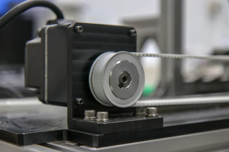
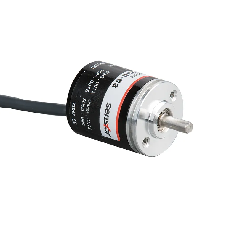
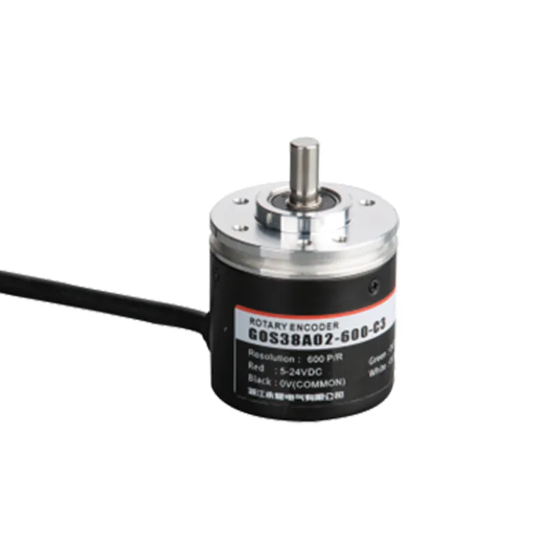
Rotary encoders are critical components in modern automation, transforming mechanical rotation into precise electrical signals. These devices measure angular position, speed, and direction, enabling control systems to execute tasks with unmatched accuracy. From industrial machinery to robotics, their role is indispensable.
This guide explores the fundamentals of rotary encoders, their operational principles, types, and practical applications. By the end, you’ll understand how to select the right encoder for your needs and leverage their capabilities in automation systems.
How Rotary Encoders Work
At its core, a rotary encoder is an electro-mechanical device that converts the angular position or motion of a shaft or axle into an electrical signal (usually digital). This signal can then be used by a control system (like a microcontroller or PLC) to determine the shaft’s position, speed, direction, or angle.
There are two main types of rotary encoders: Incremental and Absolute. They work on different principles.
Incremental Encoders
How they work: These encoders detect changes in position, not the absolute position itself. They output pulses as the shaft rotates. Counting these pulses tells you how far the shaft has turned, and analyzing the pulse patterns tells you the direction of rotation.
Key Components
- Rotating Disk: Attached to the shaft, this disk has a pattern of evenly spaced opaque and transparent segments (or reflective and non-reflective segments).
- Light Source (LED): Shines light towards the disk.
- Photodetectors (Sensors): Placed on the other side of the disk (or the same side for reflective types). They detect whether light passes through (or reflects off) the disk segments.
The Output Signals
Channel A & Channel B (Quadrature Output): Most incremental encoders have two output channels, A and B. The patterns on the disk for these channels are arranged so that the electrical signals they produce are 90 degrees out of phase (like a sine wave and a cosine wave).
- Counting Pulses: By counting the rising or falling edges of either signal A or B, you can determine the amount of rotation.
- Determining Direction: By looking at the state of signal B when signal A changes (or vice-versa), you can determine the direction of rotation. For example, if A leads B (A rises before B rises), the shaft is turning one way; if B leads A, it’s turning the other way.
- Increasing Resolution: By counting all four edges (A rising, A falling, B rising, B falling) per cycle, you can achieve 4x the resolution stated by the Pulses Per Revolution (PPR) of the encoder.
Channel Z (Index Pulse)
Often, there’s a third channel, Z, which produces a single pulse once per full revolution of the shaft. This is useful for homing or referencing – finding a known starting position.
Limitation
Because they only measure change, incremental encoders don’t know their actual position when first powered on. They need to be moved to a known reference point (often using the Z index pulse) to establish an absolute position. They also lose their position information if power is lost.
Wiring and Signal Processing
Basic Wiring Principles
- Power Supply: Typically 5–24V DC. Ensure correct polarity (Vcc/GND).
- Signal Lines: Carry pulse data (incremental) or position codes (absolute). Shielded cables minimize interference.
Signal Processing
- Incremental Encoders:
- Pulse Counting: Tracks rotation via A/B channel pulses.
- Direction Determination: Quadrature decoding distinguishes clockwise/counterclockwise motion.
- Z-Phase Signal: A single pulse per revolution for reference positioning.
- Absolute Encoders:
- Protocol Decoding: Outputs position via serial (e.g., SSI, USB) or parallel interfaces.
Signal Quality Considerations
- Anti-Interference: Use twisted-pair cables and filtering to reduce noise.
- Cable Length: Longer cables may require repeaters or differential signaling (e.g., RS-422).
Selection Guide
Key Factors to Consider
- Type:
- Incremental: Choose for continuous motion tracking.
- Absolute: Prioritize for position retention post-power loss.
- Resolution:
- Incremental: Pulses per revolution (PPR) determines precision.
- Absolute: Bits (e.g., 12-bit = 4,096 positions/revolution).
- Accuracy: The maximum deviation between actual and encoder readings.
- Output/Interface: Ensure compatibility with your controller (e.g., TTL, analog, Ethernet).
Mechanical and Environmental Specs
- Shaft Diameter: Match the motor or application requirements.
- IP Rating: Select based on exposure to dust, moisture, or chemicals.
- Operating Temperature: Critical for environments like foundries or cold storage.
- Speed Requirements: Check maximum RPM ratings for high-speed applications.
- Budget: Balance cost with performance needs (e.g., magnetic vs. optical).
Typical Application Scenarios
Industrial Automation
- Servo/Stepper Motors: Feedback for precise positioning in 3D printers or robotics.
- CNC Machines: Ensures accurate toolpath execution.
Manufacturing
- Conveyor Systems: Monitor speed and position for synchronization.
- Packaging Machinery: Aligns components during assembly.
Robotics
- Joint Positioning: Enables smooth, repeatable movements in collaborative robots.
Aerospace and Defense
- Gyroscopes: High-precision encoders stabilize drones and satellites.
Conclusion and Outlook
Rotary encoders are the unsung heroes of automation, enabling precision in everything from factory floors to space missions. As technology advances, expect trends like:
- Higher Resolution: Microfabrication techniques boosting PPR and bit counts.
- Wireless Integration: Reducing cabling complexity in IoT-enabled systems.
- AI-Driven Analytics: Real-time data processing for predictive maintenance.
In a world demanding smarter, faster automation, rotary encoders will remain foundational. Whether selecting an incremental encoder for a conveyor belt or an absolute encoder for a robotic arm, understanding their principles ensures optimal performance and reliability.


