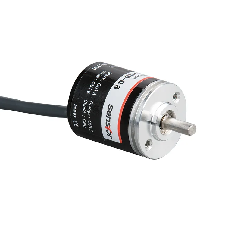
Incremental Encoder
Quadrature vs Incremental Encoder Working Principles and Selection Guide
Discover the key differences between quadrature and incremental encoders with expert insights on operation, resolution, and best selection tips.
Read More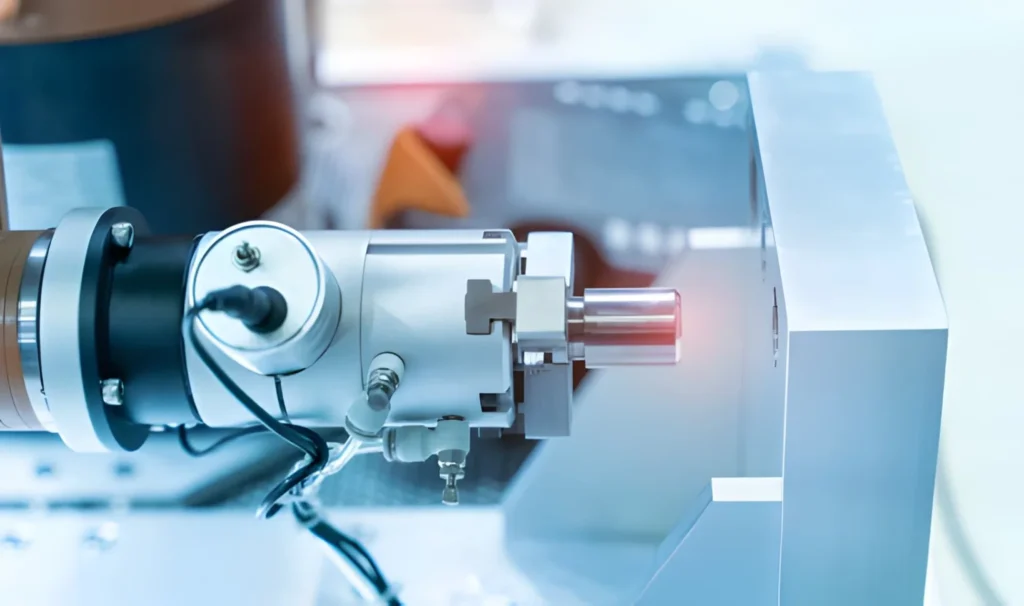
An incremental encoder is an electromechanical device that tracks changes in motion and its direction. It produces digital output signals, usually labeled A and B, that pulse a set number of times per shaft rotation. These pulses encode angular movement so a system can work out speed or relative position.
Because it gives almost instant feedback on motion changes, the incremental encoder is common in applications that need high‑precision measurement and tight motion control, such as robotics. However, it only reports how much and in which direction the shaft has moved, not its exact starting location.
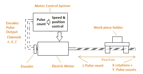
To find absolute position, the A/B signals must connect to an interface or electronic circuit that counts and processes the pulses, then sends data to a controller or counter. The system then measures all position changes relative to a fixed “home” point, which must be set each time the encoder is powered on or reset.
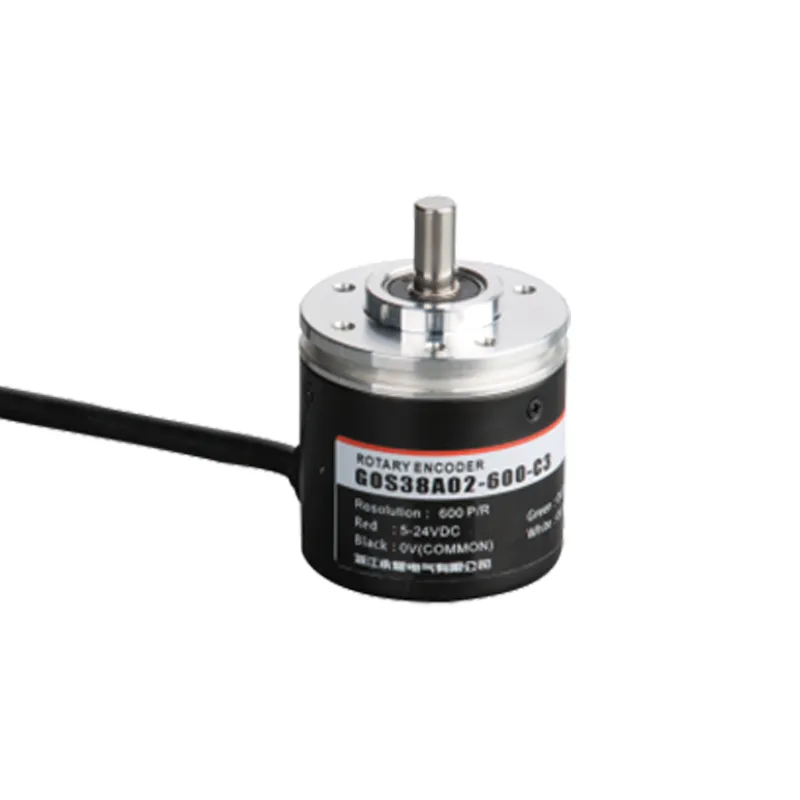
An GOS38AO3 incremental encoder works by turning shaft rotation into a stream of pulses. Each full turn produces a fixed number of pulses, called pulses per revolution (PPR). Higher PPR means finer resolution and more precise measurements.
These pulses appear as digital output signals on two channels, A and B. If only speed (RPM) matters, the system can use just the A channel. To track both speed and direction, it reads both A and B together.
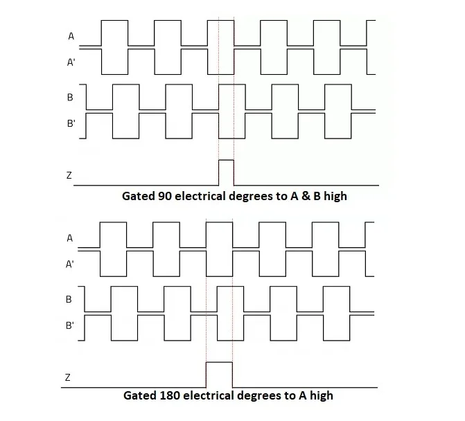
The A and B signals are offset by 90 electrical degrees, a setup known as quadrature. Over one full cycle, the encoder has 360 electrical degrees of phase, so the 90‑degree offset creates a clear lead–lag relationship. When the shaft spins at a steady speed, the output is two square‑wave signals with a 90‑degree phase difference between them.
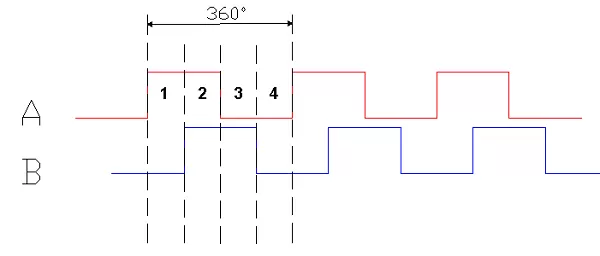
When the shaft turns the other way, the timing between the A and B signals flips. This shift lets the incremental encoder show which direction the rotation is going.
The encoder also sends another digital signal known as an index pulse, usually on a separate Z channel. This pulse appears once per full revolution. It can be used to check the count of A and B pulses, or to keep track of how many total turns the shaft has made with an external counter.
The index pulse can also help set a reference position, or “home,” by aligning the start of the Z signal with a fixed shaft orientation. Its width can be narrowed or carefully controlled to reduce errors and improve overall accuracy.
Some incremental encoders add special commutation channels labeled U, V, and W. These are timed to match the commutation signals of a BLDC motor so the controller knows exactly when to send current to each motor winding, which then creates motion.
Quantum Devices makes incremental encoders that include these built‑in commutation outputs. Their signals line up directly with a servo motor’s commutation channels, making it simpler to connect and synchronize the encoder with the motor.
Incremental encoders are widely used wherever a system needs to track motion, speed, or relative position. They most often work with motion‑control hardware to monitor and guide mechanical devices such as medical equipment, automated guided vehicles (AGVs), machine tools, and other motor‑driven machines.
They also appear in many industrial settings, including robotics, CNC machines, packaging lines, conveyors, and printing or textile equipment. In all these cases, the encoder feeds position and speed data back to a controller, which then adjusts the motor or mechanism for smoother, more precise operation.
Each Quantum Devices incremental encoder comes with a set of clear electrical, environmental, and mechanical specifications.
Electrical specifications cover:
Environmental specifications include:
Mechanical specifications list:
You can view detailed specs for each model on Quantum Devices’ incremental optical rotary encoder product page, or download their incremental encoder line card for an overview of standard configurations.
An incremental encoder has a fairly simple internal structure since it only tracks changes in position, not an absolute starting point.
A typical incremental optical encoder contains:
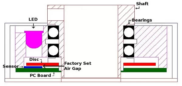
Light from the LED shines through the openings in the disc, and the photodiode converts each light pulse into an electrical pulse. Those pulses travel over the PCB and then to a user interface, where they are interpreted as motion or position data.
Quantum Devices uses a patented interlaced photodiode designed to turn light into electrical current more efficiently. Their encoders also differ in component quality and layout, which helps with easier mounting, cleaner signals, and longer operating life. The company builds all parts in‑house, which improves both supply‑chain reliability and quality control.
An incremental encoder is an electromechanical device that turns shaft rotation into a stream of pulses, used to track changes in motion and direction rather than absolute position.
They generate digital A and B output signals at a fixed number of pulses per revolution; the phase relationship between A and B indicates direction, while the pulse count and timing show speed.
The index pulse appears once per shaft rotation and helps verify channel counts, track total revolutions, or set a home position for motion‑control systems.
They are widely used in robotics, AGVs, medical equipment, machine tools, and other industrial systems where precise measurement and control of speed and relative position are needed.
Typical components include an LED light source, an interrupter disc with transparent and opaque sections, a photodiode sensor, a PCB, a solid or hollow shaft, and a protective housing.
Quantum Devices designs and builds all encoder components in‑house, using a patented interlaced photodiode and robust construction to improve signal quality, ease of installation, and service life.

Discover the key differences between quadrature and incremental encoders with expert insights on operation, resolution, and best selection tips.
Read More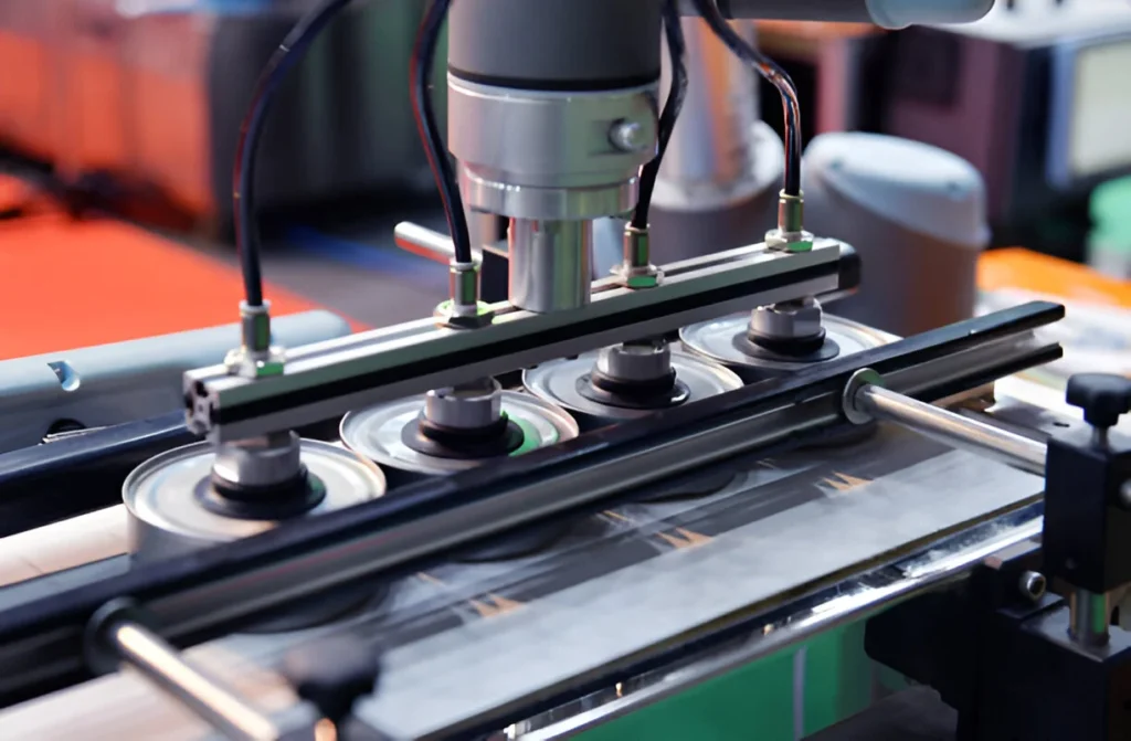
Discover what is an ATEX incremental encoder its explosion-proof design certifications and key features for safe use in hazardous industrial zones
Read More
In industrial automation and motion control, knowing exactly how far something has turned—or how fast it’s moving—can be the difference between smooth precision and costly errors. That’s where incremental shaft encoder come in. These small but powerful devices play a critical role in modern machinery, offering real-time position and speed feedback that keeps manufacturing lines, robotics, and […]
Read More