Incremental rotary encoder play a vital role in many industrial and automation applications. If you have ever wondered exactly how these devices work, what signals they output, and how to identify them, you’re in the right place. This article will take a close look at the three primary signals—Phase A, Phase B, and Phase Z—of incremental rotary encoders. Plus, you’ll learn simple techniques to distinguish these signals and understand their functions. Ready? Let’s dive in!
Introduction to Incremental Rotary Encoder Output Signals
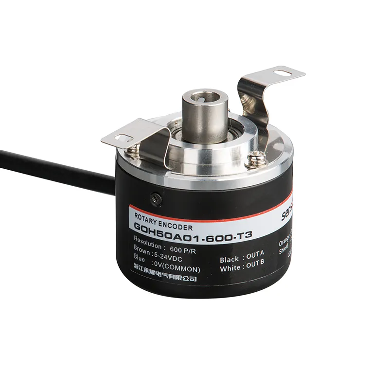
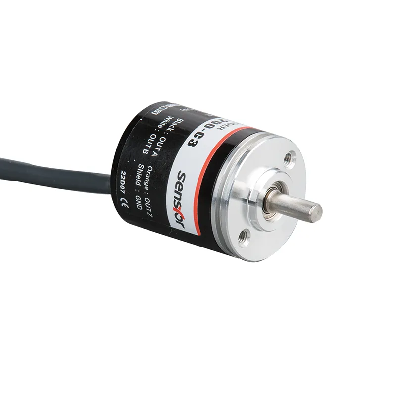
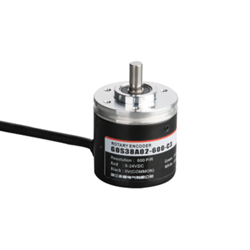
GOH50AO1 Rotary Encoder φ50mm | KOYO TRD-NH OEM Factory Incremental rotary encoder are sensors that translate rotational movement into electrical pulse signals. These devices are widely used for measuring rotation angles, position changes, speed, and direction in machinery and automation systems. The encoder’s output signals provide critical feedback to the control system, enabling precise control over mechanical movements.
Three core signals are generated by an incremental rotary encoder:
Phase A Signal
Phase B Signal
Phase Z Signal (Index Pulse)
These signals work together to give detailed information about rotation. The A and B signals are square waves with a 90° phase shift, which enables direction detection. The Z signal produces a single pulse every revolution, marking a reference point.
Understanding these signals is crucial for anyone who works with incremental rotary encoders or wants to optimize machine performance. Want to explore how these signals look and behave? Keep reading!
Phase A and Phase B outputs provide the basic “counting pulses” of an incremental rotary encoder. These two signals are square waves shifted by 90 electrical degrees. This quadrature arrangement allows the receiving system to detect not just that movement has occurred but also the direction of rotation.
When Phase A leads Phase B, the encoder shaft is rotating in one direction (e.g., clockwise).
When Phase B leads Phase A, the shaft rotates in the opposite direction (e.g., counterclockwise).
This phase difference is cleverly used in various motion control and automation systems.
Why Is the 90° Phase Difference Important?
The 90° phase shift lets electronic controllers interpret both the speed and direction of encoder rotation by analyzing which signal leads or lags. Without this offset, distinguishing direction would be impossible from pulses alone.
Common Output Types for A and B Signals
Incremental encoders provide these signals in several electrical output formats:
Output Type
Description
Typical Usage
Open Collector (NPN)
Transistor switch output, usually requiring pull-up resistors
Common in industrial control systems
Push-Pull (Totem Pole)
Actively drives both high and low states
Faster, more noise-immune signals
Line Driver (RS422)
Differential signals for long cable runs
Industrial environments with electrical noise
Quick Tip for Buyers
When selecting an incremental rotary encoder, confirm the output type matches your controller’s input requirements to avoid signal compatibility issues.
The Importance and Identification of the Phase Z Signal
What Is the Phase Z Signal?
The Phase Z signal—often called the index or zero pulse—is a unique single pulse per full revolution of the encoder shaft. Unlike the repetitive pulses of A and B, this signal only occurs once per turn, serving as a precise positional reference point.
Why Is the Z Signal Useful?
Absolute Position Reference: After continuous counting of A and B pulses, mechanical slippage or power loss might cause position errors. The Z pulse allows the system to recalibrate and confirm the actual shaft position.
Home Position: It’s often used in robots, CNC machines, and industrial systems to identify a “home” or zero position.
Speed Monitoring: Combined with A and B signals, the Z pulse can help monitor revolutions accurately.
How to Identify the Z Signal in Practice?
The Z pulse frequency is much lower since it appears only once per revolution.
On an oscilloscope, the Z pulse is a short pulse separate from the continuous waves of A and B.
Physically, it aligns with a specific mark or slot on the encoder’s disk.
If you’re setting up or inspecting an encoder, look for the unique Z pulse to ensure proper system calibration.
Signal
Frequency
Unique Feature
Phase A
Continuous
Main rotation signal
Phase B
Continuous (90° shifted)
Quadrature for direction
Phase Z
Single pulse per revolution
Reference or zero position pulse
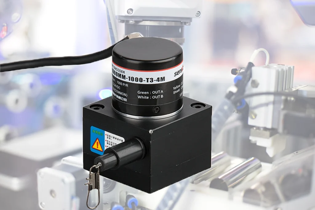
Discover how incremental rotary encoder boost precision and control in your automation projects
Recognizing these signals can seem tricky at first, but here is a practical approach:
Visualize Waveforms: Use an oscilloscope to see the signals.
A and B will show square waveforms with the same frequency but 90° out of phase.
Z will appear as a single pulse per revolution.
Phase Relation Check: Check the leading signal:
If A leads B, direction = clockwise.
If B leads A, direction = counterclockwise.
Identify the Single Pulse: Find the singular pulse in Z relative to the A and B pulses, confirming it appears once per revolution.
Table: Signal Identification Summary
Step
What to Look For
What It Tells You
Waveform Shape
Square pulses 90° phase shift
Phases A and B signals
Pulse Frequency
Continuous pulses
A and B signals
Unique Pulse
One pulse per revolution
Z signal
Direction
Which phase leads
Rotation direction
Understanding these distinctions can prevent installation or troubleshooting errors in your systems. If you want your encoder signals optimized and crystal clear, consider testing them with proper tools right after installation!
Common Applications and Benefits of Incremental Rotary Encoders
Incremental rotary encoders are everywhere—from industrial robots to printing machines, conveyor belts, and CNC equipment. Here are some of the most common use cases:
Application
Benefit
Why Incremental Encoder?
Position Monitoring
Precise shaft position control
Real-time feedback and cost-effective
Speed Measurement
RPM calculation
Quadrature output allows direction detection
Motor Feedback
Closed-loop motor control
Better motor efficiency and accuracy
Robotics & Automation
Precise movement coordination
Easy integration with controllers
Advantages Over Absolute Encoders
Feature
Incremental Encoder
Absolute Encoder
Cost
Generally cheaper
More expensive
Signal Complexity
Simple pulse signals
Complex digital position code
Power Requirement
Must have power to detect position
Maintains position without power
Error Recovery
Needs home/reference pulse
Position known immediately after power-up
If cost and simplicity matter, incremental encoders are a reliable first choice for many industries.
Tips for Choosing the Right Incremental Rotary Encoder
Selecting an encoder can be daunting. Keep these practical pointers in mind to choose the best one for your needs:
Resolution (PPR – Pulses Per Revolution): More pulses mean higher positional accuracy but also higher data processing requirements.
Output Signal Type: Match signal type (NPN, Push-Pull, RS422) with your control system inputs.
Mechanical Fit: Consider shaft type (solid, hollow), diameter, flange type, and mounting options.
Environmental Conditions: Look for encoders rated for your operating temperature, humidity, dust, or vibration levels.
Parameter
Advice
Note
Resolution
Balance between accuracy and system capability
Get advice on optimal PPR
Signal Type
Coordinate with controller specs
Incorrect match causes errors
Mechanical
Check dimensions carefully
Avoid costly installation errors
Durability
Pick industrial-grade for harsh conditions
Longevity & reliability matter
Don’t hesitate to reach out to experts or send an inquiry to manufacturers for customized needs.
Incremental rotary encoder are simple yet powerful devices essential for accurate motion control, speed measurement, and positioning in countless industrial applications. Understanding their three main output signals—Phase A, Phase B, and Phase Z—unlocks the ability to interpret direction, speed, and absolute positioning references.
Whether you’re troubleshooting, installing, or specifying encoders, knowing these signals’ characteristics will ensure smoother system integration and better machine performance. Ready to make your machinery smarter and more precise? Send an inquiry to your trusted encoder supplier today and discover the perfect incremental rotary encoder for your needs!
FAQ
What are Phase A, B, and Z signals on an incremental rotary encoder?
Phase A and B are square pulse signals with a 90° phase difference used for position and direction detection. The Z signal is a single pulse per revolution acting as a zero or reference point.
How do you determine rotation direction from the encoder signals?
By checking which of the two signals (A or B) leads in phase. If A leads B, direction is one way; if B leads A, it’s the opposite.
What is the function of the Z phase signal?
It provides a precise reference location once per revolution to help with system calibration and absolute positioning.
Can incremental encoders detect absolute position?
No, incremental encoders only measure relative movement. The Z pulse helps recalibrate but doesn’t provide true absolute position without an external reference.
How do incremental and absolute encoders differ?
Incremental encoders output relative position changes and need power to track movement, while absolute encoders provide an exact position value at any time, even after power loss.
When you’re sourcing precision feedback devices for motion control systems or automation projects, one of the first questions that comes up is simple but crucial: Should I choose an absolute or incremental rotary encoder? If you’re an engineer, a purchasing manager, or anyone involved in industrial automation, understanding this difference isn’t just a matter of preference […]
Incremental rotary encoder are essential sensors widely used in industrial automation for tracking motion, speed, and position. Unlike absolute encoders, which provide exact position information, incremental rotary encoders measure movement by generating pulses as their shaft rotates. These pulses are then interpreted to control machines, robots, conveyors, and motors with precise feedback. If you ever wondered how […]
We use cookies to enhance your browsing experience, serve personalised ads or content, and analyse our traffic. By clicking "Accept All", you consent to our use of cookies.