In the fast-paced world of industrial automation and precision engineering, one key component often determines the accuracy of motion systems — the incremental optical encoder. Whether you’re designing factory robots, upgrading conveyor systems, or maintaining CNC machinery, encoders are essential for translating mechanical motion into reliable digital feedback.
But what exactly is an incremental optical encoder, and why is it a top choice for engineers and equipment manufacturers worldwide? Let’s break it down step by step and see how it fits into modern, data-driven manufacturing.
What Is an Incremental Optical Encoder?
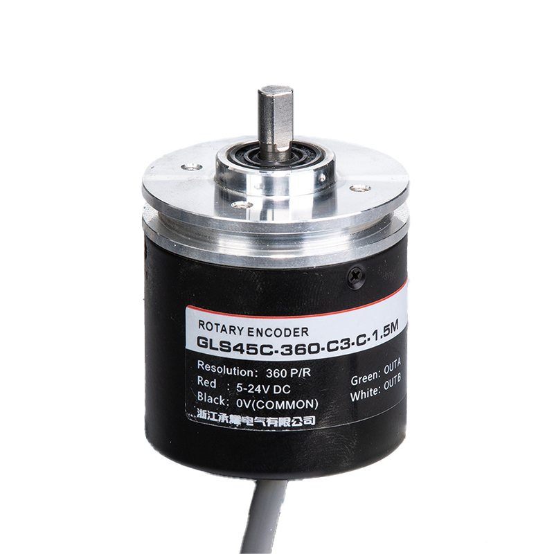
An incremental optical encoder is a type of rotary encoder that converts angular position or motion into pulses, which represent incremental changes. These pulses are read by a control system (like a PLC or motor driver) to determine speed, direction, or position.
Unlike absolute encoders that record a unique position value, incremental encoders only detect relative movement. That makes them simple, cost-effective, and highly versatile for various automation and feedback control systems.
How It Works
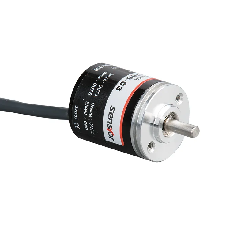
Inside an incremental optical encoder, you’ll find:
Code disk: A transparent or semi-transparent disk patterned with alternating light and dark sectors.
LED light source: Emits light that passes through the disk.
Photodetectors: Capture the light interruptions as the disk rotates.
Signal processor: Converts light-on/light-off states into electronic pulses (A, B, and Z channels).
These signals reveal rotation angle, direction (via phase difference), and reference points for calibration.
Advantages of Incremental Optical Encoders in Industrial Use
Modern production systems demand both precision and repeatability. Incremental optical encoders deliver these at an attractive price point.
Key advantages include:
High Resolution and Accuracy: Optical sensing allows fine resolution—up to thousands of pulses per revolution (PPR)—which is ideal for servo motors and robot joints.
Compact and Lightweight: Miniaturized optical designs suit embedded systems or compact automation equipment.
Cost-Effective Feedback: Compared with absolute encoders, incremental types are simpler and more affordable to integrate.
High-Speed Response: Ideal for systems needing quick acceleration detection, such as pick-and-place machines.
Easy Installation and Replacement: Standard mounting interfaces make integration into existing setups fast and maintenance straightforward.
If you’re sourcing for industrial drives or motion control modules, incremental encoders offer an excellent balance of performance and affordability — a key factor for procurement and R&D planning.
Incremental Optical Encoder vs. Absolute Encoder
One frequent question from buyers is: “Should my application use an incremental or absolute encoder?” The answer depends on your system’s performance and data requirements.
Feature
Incremental Optical Encoder
Absolute Encoder
Output
Pulse signals (relative)
Digital word (absolute position)
Startup Position
Requires homing sequence
Known at power-up
Price
Lower
Higher
Typical Use
Speed, direction, low-cost motion
Robotics, precision servos
Complexity
Simple design
More internal electronics
If your system can handle a short homing calibration at startup and you need accurate velocity or direction feedback, incremental encoders are perfect. On the other hand, if position data must be maintained after power loss, absolute encoders are worth the higher investment.
Common Applications in Industrial Automation
Incremental encoders are a mainstay in nearly every motion control system. Some popular application areas include:
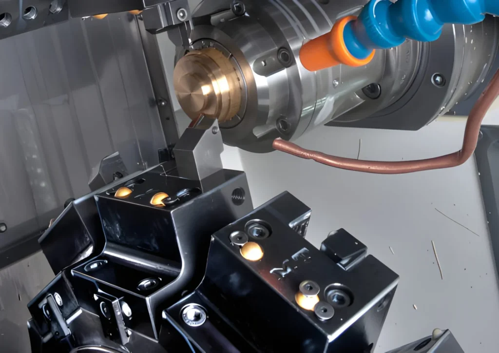
CNC Machines – For spindle and axis speed feedback.
Robotics – To track angular motion in robotic arms.
Conveyor Systems – For velocity monitoring and optimizing throughput.
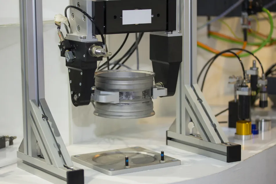
Packaging Machinery – Ensures proper synchronization between moving parts.
Elevators and Servo Drives – Controls speed consistency and safety feedback.
By providing real-time motion data, incremental encoders empower smart factories to achieve precision control and predictive maintenance.
Choosing the Right Incremental Optical Encoder
When choosing an encoder for procurement or new designs, consider the following specifications:
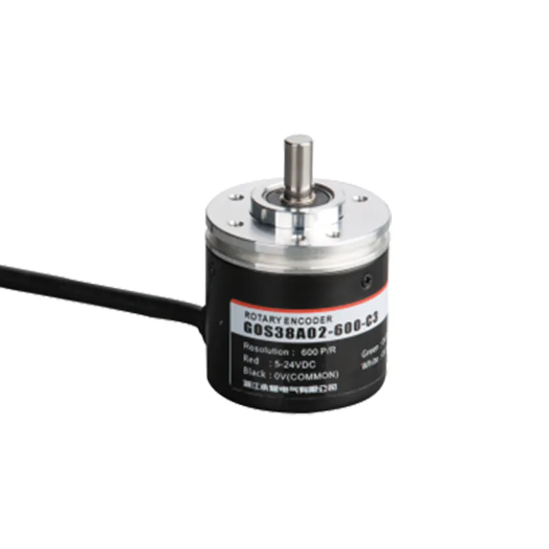
Resolution (PPR/CPR): The number of pulses per revolution defines output precision.
Shaft Type: Hollow, semi-hollow, or solid shaft designs should match your mechanical layout.
Output Signal: TTL (line driver), HTL (push-pull), or open collector outputs affect compatibility.
Mounting Style: Flange, servo, or clamping options should suit your equipment setup.
Environmental Ratings: Temperature, vibration, and IP protection ratings are crucial in harsh conditions.
Cable and Connector Type: Ensure shielded and grounded connections to reduce electrical noise.
Specification
Typical Range
Notes
Resolution
100–10,000 PPR
Higher resolution for robotics and CNC
Output Type
A/B/Z channels
Provides phase and reference indexing
Supply Voltage
5–30 VDC
Broad voltage range for industrial use
Operating Temp.
-20°C to +100°C
Check datasheet for application suitability
Professional suppliers often customize encoder housings, output cable lengths, or encoder discs to match specific OEM requirements. If your project needs a tailored solution, it’s best to send an inquiry with your required shaft size and resolution — many manufacturers can ship prototypes quickly.
How to Integrate an Incremental Optical Encoder
Integration is simpler than it sounds. Follow these main steps:
Mount the encoder securely on the motor shaft or drive axis.
Connect output channels (A/B/Z) to the PLC or motion controller.
Perform homing routine upon system start to set reference zero.
Calibrate direction and resolution in the control software.
Monitor signals to ensure clean pulse edges and no interference.
To reduce noise and signal distortion, always keep the signal cable separated from power cables and use shielded wiring—especially in frequency inverter environments.
Trends in Optical Encoder Technology
Optical encoder design continues to evolve alongside Industry 4.0 initiatives. Here are a few emerging technologies:
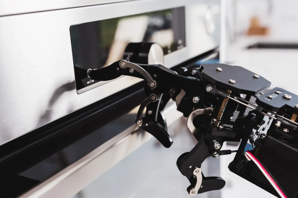
Miniaturization: Compact encoders now fit electric grippers, small servo motors, and robotics joints.
Smart Encoders with Diagnostic Functions: They can detect dust accumulation, LED degradation, or misalignment.
Higher Line Counts: New optical materials enable ultra-high-resolution encoders beyond 20,000 PPR.
Integration with IIoT Platforms: Encoders feed data directly into predictive maintenance dashboards.
For OEMs and automation engineers, adopting encoders with built-in diagnostics helps improve uptime and maintenance scheduling.
Maintenance and Lifespan Considerations
Incremental optical encoders are low-maintenance devices, but certain practices help ensure long-term reliability:
Keep the optical path clean from oil and dust.
Avoid direct mechanical shocks to the encoder housing.
Verify cable strain relief to prevent wiring fatigue.
Check LED health periodically in high-use systems.
When properly installed and protected, an optical encoder can last tens of thousands of operating hours with minimal service requirements — an important consideration for high-throughput manufacturing.
The incremental optical encoder remains a pillar of modern automation — offering precision, simplicity, and scalability across industries. Whether you’re an engineer specifying sensors for a new motion control platform or a procurement manager sourcing reliable feedback components, encoders play a silent yet critical role in every move your machine makes.
If you’re currently exploring encoder solutions for your production line or need customized encoder specifications, feel free to send an inquiry to discuss options tailored to your project. Investing in the right encoder today ensures smoother automation and better system intelligence tomorrow.
FAQ
How do I know if my encoder is incremental or absolute?
Incremental encoders output continuous pulse signals when rotating. If it outputs digital position data even when not moving, it’s likely absolute.
Can incremental encoders detect direction?
Yes. The phase difference between A and B channels determines clockwise or counterclockwise rotation.
What is the “Z” signal?
Also called an index pulse, it marks one complete revolution — used for homing and zero reference.
What affects resolution accuracy?
The precision of the code disk, photodetector alignment, and electronics all influence output quality.
Can I replace a magnetic encoder with an optical one?
In many cases, yes — especially where high resolution or cleaner signals are required. Just check mechanical fit and output compatibility.
In today’s world of industrial automation and smart manufacturing, encoders play an essential role. They help machines “see” position and movement, making precise control and feedback possible. Whether it’s a robot, CNC machine, or automated production line, encoders are key sensor devices. As a professional encoder supplier, we understand that every customer has unique needs. […]
When you’re selecting an incremental encoder, the goal is to match the device to your application’s specific demands. Do you need high-resolution feedback for a precision CNC machine, or rugged performance for a harsh industrial environment? Is low latency critical for your servo loop, or is robustness and long-term availability more important? These questions set […]
In industrial automation and motion control, knowing exactly how far something has turned—or how fast it’s moving—can be the difference between smooth precision and costly errors. That’s where incremental shaft encoder come in. These small but powerful devices play a critical role in modern machinery, offering real-time position and speed feedback that keeps manufacturing lines, robotics, and […]
We use cookies to enhance your browsing experience, serve personalised ads or content, and analyse our traffic. By clicking "Accept All", you consent to our use of cookies.