In the world of automation, robotics, and industrial equipment, precision is more than just a goal—it’s a requirement. That’s where the incremental rotary encoder comes in. This small but mighty sensor has become one of the most essential components for modern motion control systems, ensuring that machines move with accuracy, consistency, and reliability.
But what exactly is an incremental rotary encoder, and how does it compare to other encoders like absolute or optical ones? More importantly, how can it boost the performance and efficiency of your automation setup? Let’s dive deeper into the technology, applications, and benefits of using incremental rotary encoders.
What Is an Incremental Rotary Encoder?
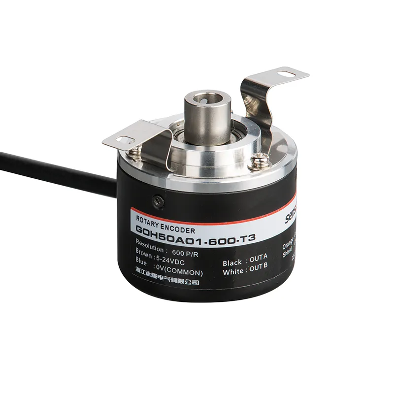
An incremental rotary encoder is a type of position sensor that measures the angular movement of a rotating shaft. Unlike an absolute encoder, which provides a unique code for each shaft position, the incremental type tracks motion by generating electrical pulses corresponding to the rotation.
Every time the encoder shaft turns, it produces a series of digital signals (A, B, and sometimes Z channels) that can be interpreted to determine speed, direction, and position change.
This pulse-based system is why incremental encoders are often used in motor feedback, linear actuators, conveyor systems, and robotics — they deliver real-time motion feedback at an affordable cost.
How Does an Incremental Rotary Encoder Work?
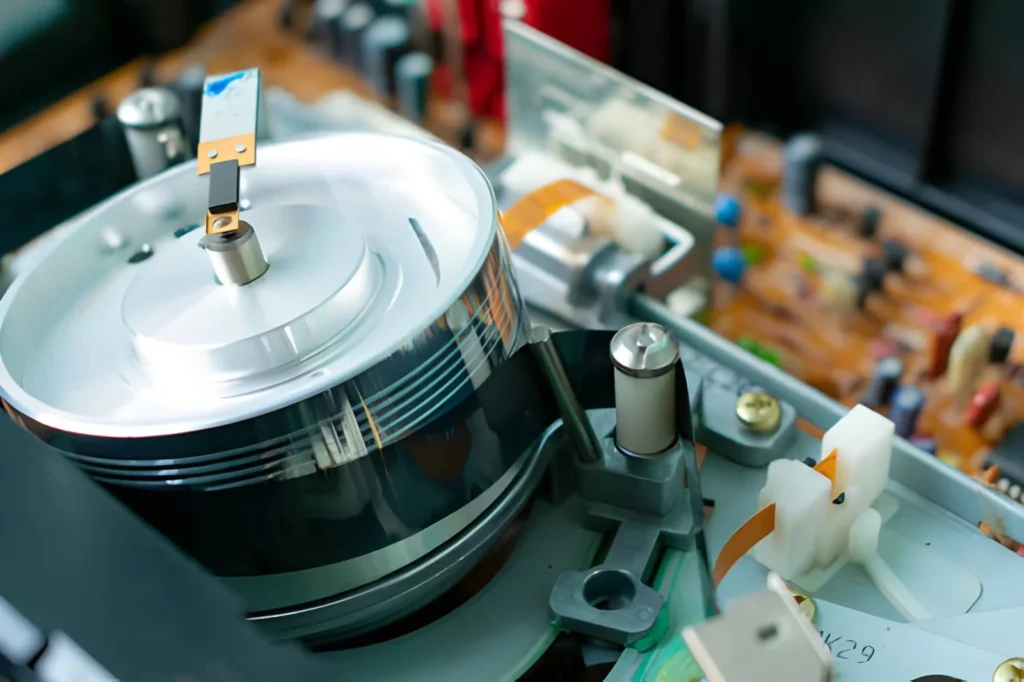
Think of an incremental encoder as a digital eye that constantly watches and counts how far a motor shaft spins. Inside the encoder, a rotating code disk with precisely spaced lines interacts with a light source (in optical encoders) or magnetic sensors (in magnetic encoders). Each time the shaft moves, those lines interrupt the light or magnetic field, creating pulses that are sent to a controller or PLC.
By counting these pulses, the system can calculate:
Angular position change
Rotational speed (RPM)
Direction of rotation
Some incremental encoders also feature an index pulse, also known as the Z-channel, which marks one specific point per revolution. This signal helps machines establish a zero or home reference point during startup calibration.
Pulse Signal Example
Channel
Function
Use Case in Control System
A
Primary pulse signal
Position tracking and speed measurement
B
90° phase-shifted pulse
Direction detection
Z
Index pulse
Reference or home position detection
Choosing Between Optical and Magnetic Incremental Encoders
When selecting an incremental rotary encoder, you’ll encounter two primary types: optical and magnetic. The choice depends largely on your application environment and required precision.
Optical encoders use light beams and gratings to generate signals with extremely high resolution—perfect for CNC machinery or semiconductor manufacturing. However, they can be sensitive to dust, vibration, or oil contamination.
Magnetic encoders, on the other hand, use Hall-effect sensors and magnetic fields to detect rotation. They’re ideal for outdoor or harsh industrial environments where dirt or moisture may be present.
Feature
Optical Incremental Encoder
Magnetic Incremental Encoder
Resolution Range
Up to tens of thousands PPR
Moderate, up to a few thousand PPR
Environmental Resistance
Low
High
Cost
Higher
More affordable
Output Stability
Very stable
Stable even under vibration
If your machinery operates in a clean, high-precision environment, optical encoders perform best. But if rugged durability matters more, a magnetic incremental rotary encoder may be the smarter choice.
Applications of Incremental Rotary Encoders
Incremental encoders are everywhere—often hidden inside motors, factory machines, or medical equipment. Their versatility lies in their ability to measure both position and motion in real time.
Industrial Automation: Used in conveyor systems and robotic arms for accurate speed and direction feedback.
CNC Machines: For spindle positioning and servo motor synchronization.
Printing Machines: Ensuring precise paper feed and registration alignment.
Elevators and Escalators: For motion control and position sensing.
Renewable Energy Systems: Wind turbine blade position monitoring.
Example Application Overview
Industry
Function
Benefit
Robotics
Joint motion feedback
Smooth, coordinated operation
Textile Machinery
Yarn tension and positioning
Improved production consistency
Packaging Equipment
Roller speed control
Accurate cutting and labeling
Renewable Energy
Turbine control feedback
Optimized energy capture
If your automation project needs precise rotary feedback, consider integrating an incremental rotary encoder. It provides a balance of simplicity, accuracy, and affordability often unmatched by other sensor types.
Incremental Encoders vs Absolute Encoders
This comparison is one of the most common questions engineers ask when selecting an encoder. The incremental rotary encoder provides relative motion feedback, which means it only knows how far something has moved from a reference point, not the exact position upon power loss.
An absolute rotary encoder, by contrast, retains its positional data even after shutdown, because each shaft angle corresponds to a unique digital code.
So which one suits your application?
Criteria
Incremental Encoder
Absolute Encoder
Data Type
Relative
Absolute
Power Cycle Memory
No
Yes
Cost
Lower
Higher
Wiring Complexity
Simple
More complex
Use Case Example
Conveyor motor feedback
Robotic arm calibration
If your machinery frequently restarts and can easily re-home, an incremental rotary encoder will be a reliable and cost-efficient choice. If you need position memory after power loss, absolute types might be worth the higher investment.
Installation Tips for Incremental Rotary Encoders
Installing an incremental encoder correctly is crucial for reliable operation and signal integrity.
❶ Align the shaft carefully: A misaligned shaft can cause bearing wear or pulse noise.
❷ Use shielded cables: Prevents EMI interference especially in high-frequency environments.
❸ Secure the mounting base: Vibrations can distort the output signals.
❹ Calibrate the zero position: Set the reference index pulse (Z-channel) to ensure synchronization.
❺ Choose proper output type: Decide between open collector, push-pull, or line driver output based on your PLC input requirements.
Output Type Comparison
Output Type
Description
Best Application Environment
Open Collector
Simple, cost-effective output signal
Short cable runs, low EMI environments
Push-Pull
Dual voltage output for better noise immunity
Moderate-length installations
Line Driver
Differential output, high noise immunity
Long-distance or high-noise systems
Need help selecting or customizing your incremental encoder setup? Feel free to contact our technical team for guidance or to request a detailed quote—we’ll help you find the right encoder for your system.
The incremental rotary encoder continues to redefine precision motion control with its simplicity, cost-effectiveness, and adaptability. Whether you’re upgrading an existing automation line or designing new industrial equipment, understanding how these encoders work will help you unlock better performance and reliability.
They might be small, but their impact on efficiency and accuracy is huge.
If you’re looking for high-quality incremental rotary encoders—optical or magnetic—tailored to your project, get in touch with us today for a competitive quote and technical support.
FAQ
What does PPR mean in an incremental encoder?
PPR stands for Pulses Per Revolution, meaning how many digital pulses are generated in one complete shaft rotation. Higher PPR offers finer movement resolution.
Can incremental rotary encoders measure direction?
Yes. The two-phase output (A and B channels) is offset by 90°, allowing detection of rotation direction based on the signal phase difference.
Are incremental encoders compatible with servo motors?
Absolutely. They are widely used for feedback control in servo systems, ensuring accurate speed and positional tracking.
What is the difference between TTL and HTL output signals?
TTL (5V logic) and HTL (10–30V logic) differ in voltage levels. HTL signals are more robust for long cable distances or noisy environments.
How do I maintain or clean an incremental encoder?
Keep it dust-free, avoid touching internal optical disks, and ensure that magnetic models are not exposed to strong stray fields. Proper maintenance extends encoder lifespan and preserves accuracy.
Incremental rotary encoder are essential sensors widely used in industrial automation for tracking motion, speed, and position. Unlike absolute encoders, which provide exact position information, incremental rotary encoders measure movement by generating pulses as their shaft rotates. These pulses are then interpreted to control machines, robots, conveyors, and motors with precise feedback. If you ever wondered how […]
Incremental Rotary Encoder Overview The Sensyor incremental rotary encoder is a precision sensor designed for accurate relative position tracking and direction detection in industrial and automation applications. Featuring quadrature output signals, this incremental shaft encoder provides reliable speed and position feedback, making it a cost-effective solution for motor control, robotics, CNC machinery, and more. Key […]
If you’ve ever wondered how machines track rotation and position so precisely, the answer often lies with an Incremental Rotary Encoder. These devices are the unsung heroes behind accurate motion control in many industries. Whether you’re working with robotics, CNC machines, or conveyor belts, understanding this technology can simplify your selection process and improve system […]
We use cookies to enhance your browsing experience, serve personalised ads or content, and analyse our traffic. By clicking "Accept All", you consent to our use of cookies.