Shaft Incremental Encoder for Motor an Machine
Choosing the right Shaft Incremental Encoder is not just about finding a sensor that outputs pulses. In real machine designs, the wrong encoder can create mounting problems, unstable feedback, signal mismatch with the controller, or poor measurement accuracy in motor and motion applications.
This article will help you understand what an Shaft Incremental Encoder does, how shaft structure changes installation and performance, where different encoder types fit best, and how to make a practical selection for motors, measuring systems, and OEM equipment. It is written for engineers, equipment manufacturers, and B2B buyers who need a clearer basis for comparing standard and customized encoder options.
What Is an Shaft Incremental Encoder?
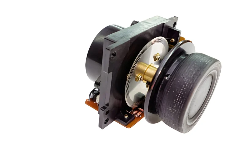
An Shaft Incremental Encoder is a rotary feedback device that generates pulse signals as the shaft rotates, allowing a control system to calculate speed, direction, and relative position by counting those pulses. In industrial systems, it is commonly used for motor feedback, synchronized motion, rotational speed monitoring, and position tracking.
Most incremental encoders use quadrature output, which means channels A and B are phase-shifted so the controller can determine direction as well as pulse count. This is why the same encoder signal can support both speed feedback and relative position monitoring when the controller is configured correctly.
Incremental encoder vs encoder sensor
The term “encoder sensor” is broad and often too vague for technical purchasing. If the actual requirement is shaft rotation feedback for a motor or moving mechanism, buyers usually need to define the encoder by output type, shaft form, mounting method, and resolution rather than stopping at the generic word “sensor.”
Is a mechanical encoder the same thing?
Not always. In many industrial searches, “mechanical encoder” may be used loosely, but an incremental rotary encoder typically refers to a device that provides structured pulse output for motion feedback rather than a general mechanical switch or basic rotation input device.
Shaft Structures and Mounting Options
The shaft structure affects more than installation convenience. It also changes coupling method, axial space, maintenance access, and the risk of alignment issues in the final machine.
The most common selection question is whether a solid shaft or hollow shaft encoder makes more sense. A solid shaft design is often straightforward when the machine already uses couplings and has enough installation space, while a hollow shaft design fits over the motor shaft and can reduce external components and packaging size.
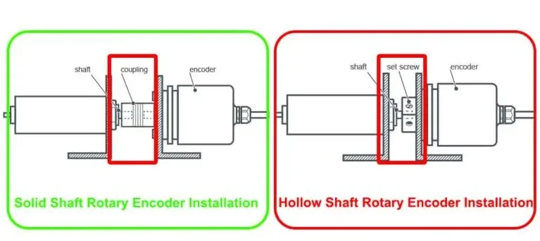
Solid shaft vs hollow shaft encoder
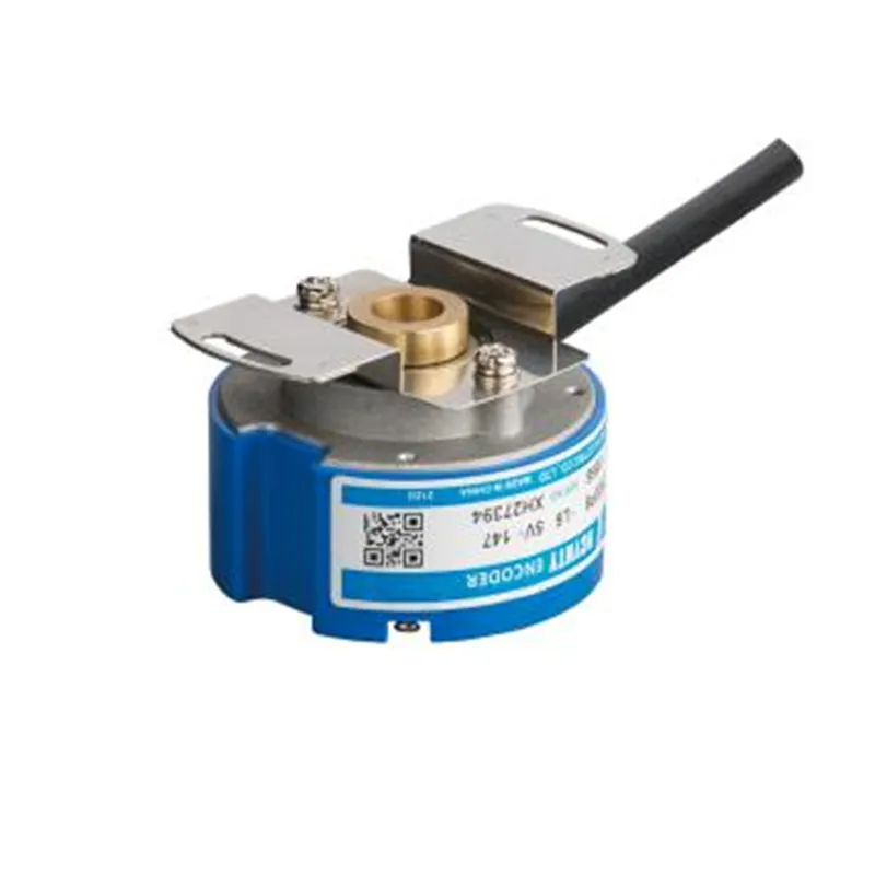
A hollow shaft encoder is often preferred in industrial motor feedback because it can mount directly over the shaft and reduce bearing load and mechanical complexity in compact assemblies. That does not mean it is always the better choice, because shaft diameter, fastening method, service access, and available mounting geometry still decide whether the design is practical.
When an encoder with wheel makes more sense
If the real target is line speed or traveled length rather than motor rotation itself, an encoder with wheel may be the better answer. Measuring wheel systems track movement directly from the material surface, which can improve accuracy in converting, printing, wire, sheet, or cut-to-length applications, provided slippage is controlled.
Where Shaft Incremental Encoder Are Used
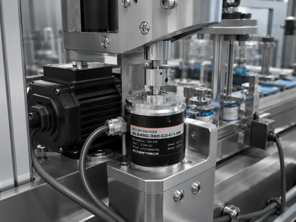
Shaft Incremental Encoders are widely used in motor feedback systems where the controller needs rotation data for speed regulation, direction detection, or synchronized movement. Common examples include servo motors in packaging and labeling machinery, drive motors in textile or conveyor systems, and compact motor assemblies where shaft-mounted feedback is preferred.
They are also used in production equipment that needs repeatable speed or position information rather than absolute position retention after power loss. Typical cases include assembly lines, robotic motion modules, packaging equipment, and rotating machinery that must report RPM, displacement, or travel count during operation.
| Application | What the encoder tracks | Key selection focus | Common structural preference |
|---|---|---|---|
| Servo motor feedback | Speed, direction, relative position | Resolution, output compatibility, compact mounting | Hollow shaft or compact shaft encoder |
| Conveyor or packaging line | Synchronized speed and movement count | Stable pulse output, controller matching, vibration tolerance | Solid or hollow shaft, depending on drive layout |
| Measuring length or web travel | Linear distance from surface movement | Wheel traction, slip control, pulses per unit length | Encoder with wheel |
| Compact OEM equipment | Relative motion feedback in limited space | Body size, shaft size, wiring direction, custom fit | Miniature hollow or compact shaft styles |
For buyers comparing models for motors or machine integration, reviewing a structured product range can help narrow down shaft form, body size, and output options before discussing exact specifications. Sensyor incremental encoder category is the right place to compare format options, and application-specific projects may also need reference to related product structures such as the GLT48 rotary encoder or 38 series rotary encoder for installation fit and size direction.
How to Choose the Right Shaft Incremental Encoder
A good selection process starts with the application, not the catalog. Before comparing models, confirm whether the encoder is tracking motor rotation, output shaft movement, roller speed, or material travel, because each setup changes the best shaft form and resolution strategy.
Resolution is one of the most discussed parameters, but it should be matched to the control requirement rather than maximized automatically. Incremental encoders are commonly specified in pulses per revolution, and the usable result also depends on how the controller counts the A and B channels in X1, X2, or X4 mode.
Output type matters just as much as resolution. Many industrial applications rely on quadrature A/B outputs, while specific control systems may require electrical formats such as TTL, HTL, or differential signaling that fit the receiving controller and cable environment.
Installation details are equally important. Shaft diameter, housing size, mounting flange, cable direction, and available space around the motor or machine frame can quickly eliminate otherwise suitable models.
Environmental conditions should also be checked early. Dust, oil mist, vibration, and continuous-duty cycles can influence whether a compact encoder is acceptable or whether a more industrial-duty mechanical arrangement is needed.
When customization is the better option
A standard encoder is usually the faster choice when the shaft size, output format, and mounting interface are already conventional. A customized encoder becomes more relevant when the project has non-standard shaft dimensions, tight packaging, special cable direction, controller-specific output, or OEM mechanical constraints that make standard formats inefficient.
If our current products do not meet your requirements, please contact us and provide us with your project details and requirements.
Common Selection Mistakes
One frequent mistake is choosing the highest available resolution without checking whether the control system can actually use it. Higher resolution is not automatically better if the application only needs moderate speed tracking, or if controller counting mode and response limits make extra pulses unnecessary.
Another common mistake is focusing on electrical parameters first and leaving shaft details for later. In practice, many encoder problems come from mismatched shaft diameter, coupling layout, flange geometry, or lack of mounting space rather than from the pulse output itself.
For measuring wheel applications, buyers often underestimate slip. A wheel encoder can be very effective for length or surface speed measurement, but friction, contact pressure, and material condition directly affect real accuracy.
If your team has already defined shaft type, installation size, signal format, and target resolution, a quick model review with a manufacturer can shorten the selection cycle and reduce redesign risk for ODM or retrofit projects.
FAQ
What does an Shaft Incremental Encoder do in a motor system?
It converts shaft rotation into pulse signals that a controller can use to calculate speed, direction, and relative position. In motor systems, it is commonly used for feedback in servo drives, synchronized motion, and speed regulation.
What is the difference between a hollow shaft encoder and a solid shaft encoder?
A solid shaft encoder usually connects through a coupling, while a hollow shaft encoder fits over the motor shaft directly and is clamped in place. Hollow shaft designs are often more compact, but the right choice still depends on shaft size, mounting geometry, and service conditions.
How do I choose the right resolution for an Shaft Incremental Encoder?
Start from the motion accuracy your application needs and then check how the controller counts encoder edges. The required PPR depends on the mechanical movement per revolution and whether the control system uses X1, X2, or X4 counting.
Can an Shaft Incremental Encoder be used with a measuring wheel?
Yes. A measuring wheel encoder is a common way to convert rotary pulses into linear distance or surface speed data in applications such as converting lines, printing, conveying, and cut-to-length systems. The main condition is controlling slip between the wheel and the material surface.
When should I choose a customized encoder instead of a standard model?
Choose customization when standard shaft sizes, body dimensions, mounting style, cable direction, or output format do not fit your machine. This is especially common in compact OEM equipment or projects with non-standard mechanical interfaces.
Is a mechanical encoder the same as an incremental rotary encoder?
Not necessarily. “Mechanical encoder” can be used loosely in search language, but an incremental rotary encoder usually refers to a structured motion feedback device that outputs pulse signals for industrial control or measurement.