Quadrature Encoder Signal Selection and Industrial Use
A quadrature encoder looks simple from the outside: a shaft turns, wires leave the housing, and the controller receives pulses. Yet this small device can decide whether a machine moves accurately, cuts at the right length, or slowly drifts away from its target until everyone.
A quadrature encoder provides more than pulse count. By generating two signals with a controlled phase relationship, it allows a controller to determine relative position, speed, and direction. That makes it a practical feedback device for servo systems, conveyors, CNC machinery, packaging equipment, robotics, printing machines, and many other motion-control applications.
The key is not simply choosing the highest PPR available. You need the right mechanical structure, electrical output, response frequency, protection level, cable arrangement, and controller compatibility. A very high-resolution encoder connected to the wrong PLC input is still the wrong encoder. It is just an expensive way to produce confusing numbers.
Behind the signal-level details, Sensyor develops rotary encoders and industrial sensing products for motion-control applications, including incremental, absolute, optical, and magnetic encoder solutions. With in-house R&D and manufacturing support, Sensyor helps OEMs, machine builders, and automation integrators specify encoder configurations around shaft design, resolution, output interface, and operating conditions—rather than forcing a machine to adapt to a one-size-fits-all encoder.
What Is a Quadrature Encoder?
A quadrature encoder is an incremental encoder that outputs two pulse channels, usually called Channel A and Channel B. These channels are offset by 90 electrical degrees. The controller compares which channel changes first to determine the direction of rotation.
When the shaft rotates in one direction, A leads B. When it rotates in the opposite direction, B leads A. The controller counts the pulse transitions to determine how far the shaft has moved.
In industrial equipment, a rotary quadrature encoder is commonly used when the machine needs feedback such as:
- Motor speed in RPM
- Relative shaft position
- Conveyor travel distance
- Rotation direction
- Index or home position
- Synchronization between two moving axes
Unlike an absolute encoder, an incremental quadrature encoder does not know its true mechanical position immediately after power-up. It knows movement relative to a reference point. For this reason, many machines perform a homing routine at startup.
How Does a Quadrature Encoder Work?
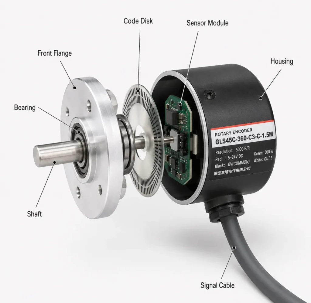
To understand how does a quadrature encoder work, imagine two sensors observing the same rotating code disc or sensing structure from slightly different positions.
As the shaft rotates, Channel A and Channel B produce square waves. The phase shift between them is normally 90 electrical degrees.
| Signal | Main Function | Typical Use |
|---|---|---|
| A phase | Primary pulse channel | Position and speed counting |
| B phase | Phase-shifted pulse channel | Direction detection |
| Z phase | One pulse per revolution | Home reference, reset, index positioning |
For clockwise rotation, Channel A may lead Channel B. For counterclockwise rotation, Channel B may lead Channel A. However, always confirm the actual direction convention in the encoder datasheet and machine wiring diagram. “Clockwise” depends on the viewing direction, and mechanical drawings have ended more than one engineering debate.
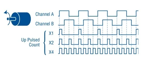
A quadrature encoder can be counted in several ways:
- x1 counting: Count one edge of Channel A.
- x2 counting: Count rising and falling edges of Channel A.
- x4 counting: Count both rising and falling edges of A and B.
A 1000 PPR encoder can therefore produce up to 4000 counts per revolution in x4 decoding mode. This does not change the physical encoder resolution. It changes how finely the controller interprets each cycle.
Quadrature vs Incremental Encoder What Is the Real Difference?
The phrase “quadrature vs incremental encoder” can be misleading because the two terms describe different things.
An incremental encoder is a category of encoder. It produces pulses that represent movement from a reference point. A quadrature encoder is usually an incremental encoder that uses A/B channels with a 90-degree phase shift.
| Encoder Type | Signal Form | Direction Detection | Position at Power-Up |
|---|---|---|---|
| Single-channel incremental encoder | A only | No | Relative only |
| Incremental encoder with A/B | Quadrature | Yes | Relative only |
| Incremental encoder with A/B/Z | Quadrature plus index | Yes | Relative with reference point |
| Absolute encoder | Digital or serial position code | Yes | Known immediately |
In other words, not every incremental encoder is necessarily a quadrature encoder. A single-channel pulse encoder can measure speed, but it cannot independently confirm direction. Once an incremental encoder includes A and B channels, it becomes suitable for quadrature decoding.
For most industrial motion-control tasks, A/B signals are preferred because direction is not optional. If a conveyor reverses during fault recovery, or a servo axis moves backward during tuning, the controller needs to know that immediately.
Optical Quadrature Encoder vs Magnetic Quadrature Encoder
An optical quadrature encoder typically uses a light source, code disc, and optical sensor to create pulse signals. A magnetic quadrature encoder uses magnetic sensing technology, often based on Hall-effect or magnetoresistive sensing structures.
Neither technology is automatically “better.” The correct choice depends on the mechanical environment and control requirement.
| Comparison Point | Optical Quadrature Encoder | Magnetic Quadrature Encoder |
|---|---|---|
| Sensing principle | Light passing through or reflecting from a coded structure | Magnetic field detection |
| Typical advantage | High-resolution industrial feedback options | Compact, contactless sensing options |
| Main design concern | Optical path contamination and disc alignment | Magnet alignment and field stability |
| Suitable scenarios | Servo systems, CNC, packaging, precision automation | Compact equipment, special mounting structures, embedded motion sensing |
| Selection priority | Signal accuracy, PPR range, conventional industrial integration | Mechanical simplicity, package size, magnetic design compatibility |
An optical quadrature encoder is often a strong choice for conventional industrial automation systems where standard shaft mounting, high PPR options, and well-defined output formats are important.
A magnetic quadrature encoder can be attractive when the system benefits from contactless magnetic sensing, compact construction, or a different mechanical arrangement. Still, magnetic does not mean “install anywhere and forget it.” Magnet centering, air gap, external magnetic fields, and mounting tolerance all matter.
Upgrade your motion control system with Sensyor encoders; we provide product catalogs, technical specifications, and customized services.
PPR, CPR, RPM, and Response Frequency
PPR means pulses per revolution. It describes how many output cycles an encoder generates during one full shaft rotation.
However, PPR is not the same as the actual count value seen by the controller.
For example:
- Encoder resolution: 2500 PPR
- Controller decoding mode: x4
- Effective count value: 10,000 counts per revolution
The line frequency can be estimated with this formula:
Frequency = PPR × RPM ÷ 60
Suppose a 2500 PPR quadrature encoder runs at 3000 RPM:
2500 × 3000 ÷ 60 = 125,000 Hz
That means the encoder output frequency is 125 kHz per channel. With x4 decoding, the controller may process up to 500,000 count events per second.
This is where many selection mistakes begin. Buyers see “high PPR” and assume it must be more accurate. But if the PLC, motion controller, high-speed counter, or MCU cannot process the signal frequency, the system can lose counts.
Before choosing PPR, confirm:
- Maximum shaft speed
- Maximum controller input frequency
- Required positioning precision
- Mechanical transmission ratio
- Decoding mode
- Noise conditions and cable length
A lower-PPR encoder that the controller can read cleanly is usually more useful than a high-PPR model that produces missed pulses at full speed.
Choosing the Right Output Interface
The output circuit is just as important as the encoder body. Your encoder and controller must agree electrically before they can agree mechanically.
| Output Type | Best For | Main Consideration |
|---|---|---|
| Open collector | Basic PLC input circuits | Requires compatible pull-up arrangement |
| Push-pull / complementary | Flexible industrial inputs | Supports sourcing or sinking signal behavior |
| TTL / 5 V | Low-voltage motion controllers and embedded systems | Check voltage compatibility carefully |
| HTL / 24 V | Industrial PLC systems | Suitable for common 24 V control environments |
| Line driver / differential output | Long cables and high-noise environments | Requires compatible differential receiver |
For short, clean cable runs inside a compact machine, TTL or low-voltage differential output may be practical. For 24 V PLC systems, HTL or push-pull output is often easier to integrate.
For long cable routes, inverter cabinets, servo drives, welding equipment, or high electrical noise, differential line-driver output deserves serious attention. It improves noise immunity because the receiver evaluates the difference between paired signals rather than relying on a single line referenced to ground.
When sourcing from a manufacturer, supplier, or China factory, ask for more than a wiring color chart. Request the output circuit diagram, maximum response frequency, supply-voltage range, output current, cable specification, and recommended receiving circuit.
Where Quadrature Encoders Make a Difference
A quadrature encoder is most valuable when the machine must measure movement and react to direction changes in real time.
Servo Motor Feedback
Servo systems use encoder feedback to compare commanded movement with actual movement. A/B signals provide incremental feedback for speed and relative position control, while Z phase can support homing or reference alignment.
CNC Machine Tools
In CNC equipment, encoder feedback is used for spindle speed monitoring, feed-axis movement, tool positioning, and rotary table control. Poor signal quality can lead to inconsistent motion, inaccurate machining, or alarms that appear only when the machine runs at full speed.
Packaging and Labeling Equipment
Packaging lines must synchronize film feeding, sealing, cutting, labeling, and product spacing. An encoder helps the machine measure actual movement rather than assuming the motor always behaves perfectly. Motors, sadly, do not read production schedules.
Conveyors and Material Handling
A quadrature encoder can measure belt travel distance, speed, and reverse movement. This is useful for sorting, indexing, length measurement, pallet positioning, and accumulation systems.
Printing and Textile Machinery
Printing machines use feedback for registration control and roller synchronization. Textile equipment uses encoder signals to monitor winding speed, roll position, and material feed consistency.
A Practical Quadrature Encoder Selection Checklist
Use this checklist before requesting a quotation or comparing encoder models.
| Selection Item | Questions to Confirm |
|---|---|
| Shaft structure | Do you need solid shaft, hollow shaft, through-hole, or blind hollow shaft? |
| Housing size | Is installation space limited to 25 mm, 38 mm, 40 mm, 48 mm, 50 mm, or another size? |
| Resolution | What PPR is required after considering the transmission ratio and controller decoding mode? |
| Output signal | Do you need A/B, A/B/Z, complementary A/B, or differential A/B/Z output? |
| Supply voltage | Does your system use 5 V, 12 V, or 24 V control power? |
| Cable distance | Is the encoder near the controller, or does the signal travel through a long cable route? |
| Environment | Are there vibration, dust, oil mist, moisture, electrical noise, or temperature concerns? |
| Controller input | Is the receiving device a PLC, servo drive, high-speed counter, MCU, or motion-control card? |
For a 24 V industrial machine with longer cable routing, a configuration such as the GLS50H can be a practical starting point. It supports A/B/Z signal options, multiple resolution choices, a push-pull output structure, and a 50 mm solid-shaft housing for conventional industrial installation.
For compact automation equipment, smaller encoder housings may be more suitable. For servo motor feedback, resolution, coupling geometry, and signal compatibility should be reviewed as a complete system rather than purchased as separate checkboxes.
A capable OEM/ODM encoder factory should be able to discuss PPR, output type, shaft dimensions, cable direction, connector style, mounting structure, and application-specific testing before production begins.
Installation Mistakes That Cause Counting Errors
Even a correctly selected quadrature encoder can fail in practice because of installation and wiring problems.
Watch for these common issues:
- Using a rigid coupling that transfers motor shaft misalignment into encoder bearings
- Running encoder cables beside motor cables or VFD output cables
- Leaving shield grounding inconsistent between the cabinet and machine frame
- Connecting 24 V HTL signals directly to a 3.3 V MCU input
- Exceeding the controller’s maximum high-speed counter frequency
- Ignoring vibration and radial shaft load
- Using the wrong A/B direction convention in the control program
- Forgetting to use the Z phase when the machine requires repeatable homing
Use flexible couplings where appropriate, separate encoder wiring from power wiring, and follow the supplier’s shielding recommendation. In noisy industrial applications, the cable route is part of the signal design—not an afterthought added by whoever gets to the cable tray last.
Teensy 4.1 Quadrature Encoder Considerations
A Teensy 4.1 quadrature encoder project can use interrupt-based counting or dedicated hardware resources, depending on the library and pin assignment. The board is fast enough for many motion and measurement projects, but signal conditioning still matters.
Before connecting an industrial encoder to Teensy 4.1, confirm:
- The encoder output voltage is compatible with the board input level
- A 24 V encoder output is converted safely before it reaches the MCU
- Differential outputs use an appropriate receiver circuit
- Cable length and noise are controlled
- The selected pins support the intended decoding method
- The software count mode matches the expected PPR and mechanical ratio
For laboratory or prototype work, interrupt decoding can be sufficient. For high-speed motion systems, use hardware quadrature decoding or a dedicated counter interface whenever possible. The MCU should spend its time controlling the machine, not desperately trying to count edges it already missed.
If you are unsure which type of encoder is best suited for your project, please contact us immediately for a customized encoder or sensor solution.
The right quadrature encoder is not determined by PPR alone. Start with the machine’s mechanical structure, then confirm maximum speed, required count resolution, controller input type, cable length, output circuit, and environmental conditions.
For most industrial projects, an A/B/Z incremental encoder with a correctly matched output circuit gives the best balance of direction feedback, repeatable homing, and integration flexibility. For compact machines, prioritize mounting space and shaft geometry. For long cable runs or electrically noisy cabinets, prioritize differential transmission and shielding strategy.
Send your shaft size, target PPR, maximum RPM, controller input type, cable distance, and operating environment for a practical configuration review before finalizing the model.
FAQ
How does a quadrature encoder work?
A quadrature encoder outputs two pulse channels called A and B. The channels are shifted by 90 electrical degrees, allowing the controller to identify speed, relative movement, and rotation direction by comparing their sequence.
What is the difference between a quadrature encoder and an incremental encoder?
An incremental encoder produces pulses that represent relative movement. A quadrature encoder is usually an incremental encoder with A/B phase-shifted outputs that allow direction detection. Some incremental encoders provide only one pulse channel and cannot determine direction independently.
What is the difference between PPR and quadrature counts?
PPR refers to pulse cycles per revolution generated by the encoder. Quadrature counts depend on the controller decoding mode. A 1000 PPR encoder can produce 1000, 2000, or 4000 counts per revolution using x1, x2, or x4 decoding.
Is an optical quadrature encoder better than a magnetic quadrature encoder?
Not necessarily. Optical designs are common in industrial precision feedback systems, while magnetic designs can suit compact or contactless sensing arrangements. The best choice depends on resolution, environment, mounting, output interface, and controller requirements.
Can Teensy 4.1 read a quadrature encoder?
Yes. Teensy 4.1 can read quadrature signals through software libraries, interrupts, and hardware resources. However, the encoder output voltage must be compatible with the board input level, especially when using industrial 24 V encoder outputs.