High Precision Incremental Encoder Selection Guide
A high precision incremental encoder is often selected after a motion system has already shown its first warning signs: unstable speed feedback, poor repeat positioning, missed pulses, or a machine that behaves perfectly in the workshop but becomes unpredictable on the production floor.
The easy reaction is to request more pulses per revolution. That is understandable, but it is not always the right answer. A higher PPR value can improve measurement granularity, yet it cannot correct shaft misalignment, cable noise, poor grounding, vibration, controller limits, or an unsuitable output signal.
To select a high precision incremental encoder properly, you need to look at the complete feedback chain: mechanical motion, encoder technology, output format, installation method, cable path, controller input, and operating environment.
At Sensyor, encoder selection begins with the machine requirement rather than the largest number printed on a datasheet. The available incremental rotary encoder range includes compact, solid-shaft, hollow-shaft, optical, magnetoelectric, high-resolution, and OEM-configurable options for industrial motion systems.

What Makes a High Precision Incremental Encoder “High Precision”?
A high precision incremental encoder converts rotation into electrical pulses that a PLC, servo drive, motion controller, counter, or display can interpret as speed, direction, relative position, or revolution count.
However, “high precision” is not one single specification. It usually involves three separate factors:
| Term | What It Means | Why It Matters |
|---|---|---|
| Resolution | Pulses or counts generated per revolution | Determines the smallest detectable motion increment |
| Accuracy | How closely the measured position matches actual position | Affects true positioning performance |
| Repeatability | Ability to return to the same measured position repeatedly | Important for indexing, cutting, feeding, and pick-and-place cycles |
A 10,000 P/R encoder may provide fine pulse resolution, but the total system can still miss its target if the coupling slips, the shaft vibrates, the controller input frequency is too low, or the cable introduces electrical noise.
In other words: more pulses are useful, but more pulses are not magic.
Before selecting an encoder, define these points:
- Required speed range in RPM
- Required minimum movement or positioning increment
- Maximum allowable position error
- Controller or PLC input frequency limit
- Need for direction recognition
- Need for a home or reference position
- Shaft type and available mounting space
- Cable length and electrical noise level
For example, encoder output frequency rises with both PPR and shaft speed:
Output Frequency = PPR × RPM ÷ 60
A 5,000 P/R encoder operating at 3,000 RPM can produce 250 kHz per channel. The controller, cable, and output circuit must be able to handle that signal without distortion or missed transitions.
Resolution, Accuracy, and Repeatability Are Not the Same Thing
One common purchasing mistake is using resolution as the only definition of performance.
Resolution tells you how many signal divisions are available during one revolution. Accuracy tells you how close the reported angle or position is to the true physical value. Repeatability tells you whether the encoder can return to the same result every time the axis moves to the same location.
A high-resolution encoder mounted with a poor coupling can produce a very detailed report of a mechanical problem. That is not an upgrade.
For CNC axes, servo motors, precision packaging stations, and robotic joints, the best high precision encoder selection considers both electrical resolution and mechanical stability. Shaft runout, coupling quality, bearing condition, mounting concentricity, vibration, and thermal movement can all influence the final result.
Select the Right Output: A, AB, ABZ, or Differential Signals
An incremental rotary encoder can offer several output arrangements. The correct choice depends on what the controller needs to know.
| Output Type | Typical Use | Key Benefit |
|---|---|---|
| A Phase | Basic speed or pulse counting | Simple and economical |
| A/B Quadrature | Speed, direction, and relative position | Identifies rotational direction |
| A/B/Z | Motion control with home reference | Adds one index pulse per revolution |
| Differential A/A̅, B/B̅, Z/Z̅ | Long cable runs or high-noise systems | Better noise rejection |
The phrase quadrature vs incremental encoder can be misleading. A quadrature encoder is normally a type of incremental encoder. “Incremental” describes the relative pulse-based measurement method, while “quadrature” describes the A/B signal relationship.
A rotary quadrature encoder uses two channels offset by 90 electrical degrees. This phase offset allows the controller to determine whether the shaft is rotating clockwise or counterclockwise.
An incremental quadrature encoder is therefore a good fit when a machine needs relative position and direction feedback. Adding a Z phase is useful when the system needs a repeatable reference point once per revolution.
A magnetic quadrature encoder can also provide A/B signals. The choice between magnetic and optical sensing should depend on your required resolution, environment, mounting arrangement, and signal requirements.
Magnetoelectric Encoders vs Optical Encoders
Magnetoelectric Encoders and optical encoders both serve industrial motion-control applications, but they are not interchangeable in every project.
| Selection Factor | Magnetoelectric Encoder | Optical Encoder |
|---|---|---|
| Typical Strength | Compact design and tolerance for demanding industrial conditions | High resolution and fine motion feedback |
| Best Fit | General automation, compact equipment, vibration-prone environments | Servo systems, CNC equipment, robotics, high-resolution positioning |
| Resolution Potential | Depends on design and signal processing | Often suitable for high-PPR feedback requirements |
| Environmental Consideration | Consider nearby magnetic fields and electrical installation quality | Consider contamination, sealing, vibration, and application conditions |
| Signal Options | Can support A, AB, ABZ, and differential designs | Can support high-resolution incremental output formats |
The right technology depends on the machine—not the marketing label.
For a compact packaging machine with limited installation space and moderate resolution demand, a magnetoelectric incremental shaft encoder may be the practical choice. For a high-speed servo system where fine motion increments and high PPR values are essential, an optical high precision encoder may be more appropriate.
Always verify the actual operating conditions: temperature, vibration, dust, moisture, motor noise, cable routing, shaft loading, and controller compatibility.
Rotary Encoder or Optical Linear Encoder?
A rotary encoder measures angular motion. An optical linear encoder measures direct linear movement.
This distinction matters in high-precision machine design.
A rotary encoder mounted on a motor or screw measures the rotation of that component. It does not automatically measure every mechanical effect between the motor and the moving load. Backlash, screw pitch error, belt stretch, coupling compliance, and thermal expansion can all influence the actual linear position.
An optical linear encoder measures the moving axis directly. It may be a better option when a machine requires direct feedback of table movement, especially in high-accuracy machine tools, precision inspection equipment, or axes where transmission error must be minimized.
Choose an incremental rotary encoder when you need dependable rotational feedback from a motor, shaft, roller, spindle, conveyor, or rotating machine part.
Choose an optical linear encoder when direct linear-axis position is more important than motor rotation data.
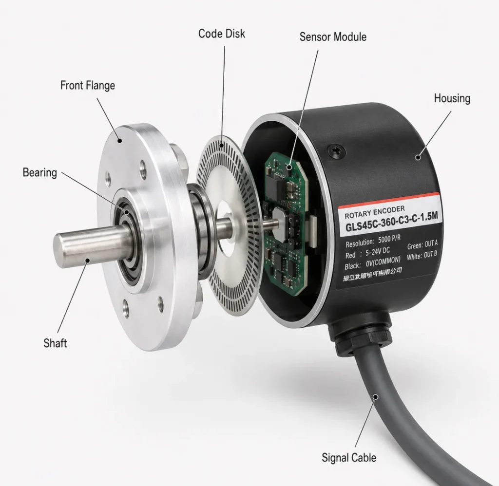
Mechanical Selection: Shaft, Housing, Coupling, and Mounting
Mechanical installation is where many encoder projects quietly succeed or fail.
A high precision incremental encoder should match the physical structure of the machine:
- Solid-shaft encoder: Suitable for coupling to a motor shaft, roller, spindle, or machine shaft.
- Through-hole or hollow-shaft encoder: Useful where the encoder mounts directly around an existing shaft.
- Compact housing: Important for small automation modules, feeders, compact robots, and packaging machinery.
- Heavy-duty housing: Better suited to vibration, shock, large shafts, and demanding industrial equipment.
Avoid placing excessive radial or axial load on the encoder shaft. Use an appropriate flexible coupling to compensate for small alignment errors without transmitting damaging forces to the encoder bearing.
Do not treat the coupling as a minor accessory. In a precision feedback system, it is part of the measurement system.
Signal Quality: Long Cables, EMI, and Controller Inputs
The encoder does not stop working at the housing. Its signal still needs to travel through the cable, connector, panel, drive, PLC input, and control logic.
Long cable runs, high capacitance, electromagnetic interference, and weak grounding can reduce signal quality. In industrial environments, nearby VFDs, servo drives, contactors, motors, and switching power supplies can create electrical noise that affects encoder feedback.
For long-distance or high-noise applications, consider these practices:
- Use shielded encoder cable rather than unshielded general-purpose wire.
- Use twisted-pair conductors for signal lines where appropriate.
- Keep encoder cables separate from motor power cables and high-current wiring.
- Select low-capacitance cable for long transmission paths.
- Use differential output when the controller supports it.
- Select connectors with suitable sealing, strain relief, and field-service requirements.
- Confirm grounding practice with the control-system design rather than assuming one rule fits every installation.
For example, the GOS40A high-resolution rotary encoder is available with up to 10,000 P/R and a 24V line-driver option designed for long-distance transmission applications. That makes the cable and receiving device part of the selection conversation, not an afterthought.
For commissioning, validation, and pulse-frequency monitoring, the CY7 High-Frequency Counter can help engineers verify encoder output signals during machine setup or maintenance.
A Practical High Precision Incremental Encoder Selection Process
Use this sequence before requesting a quotation from an encoder manufacturer, supplier, or OEM factory.
| Step | Key Question | Selection Impact |
|---|---|---|
| 1. Define the motion | Are you measuring speed, position, direction, or all three? | Determines A, AB, or ABZ output |
| 2. Calculate resolution | What PPR is needed at the actual shaft speed? | Prevents over-specification or controller overload |
| 3. Check controller input | What voltage, frequency, and interface can the controller accept? | Determines TTL, HTL, push-pull, open collector, or differential output |
| 4. Confirm mechanical fit | Is the shaft solid, hollow, large, small, or space-limited? | Determines encoder body, shaft form, and mounting |
| 5. Assess the environment | Is there vibration, dust, moisture, EMI, or a long cable path? | Determines protection, technology, cable, and output type |
| 6. Validate before scaling | Has the signal been checked at actual operating speed? | Reduces installation risk before batch production |
Sensyor High Precision Incremental Encoder Options
The following examples show how different product structures can match different machine requirements.
| Application Requirement | Suggested Sensyor Option | Why It Fits |
|---|---|---|
| Compact machine with limited installation space | GOS25C φ25 mm Rotary Encoder | Compact body, up to 4096 P/R options, suitable for narrow automation equipment |
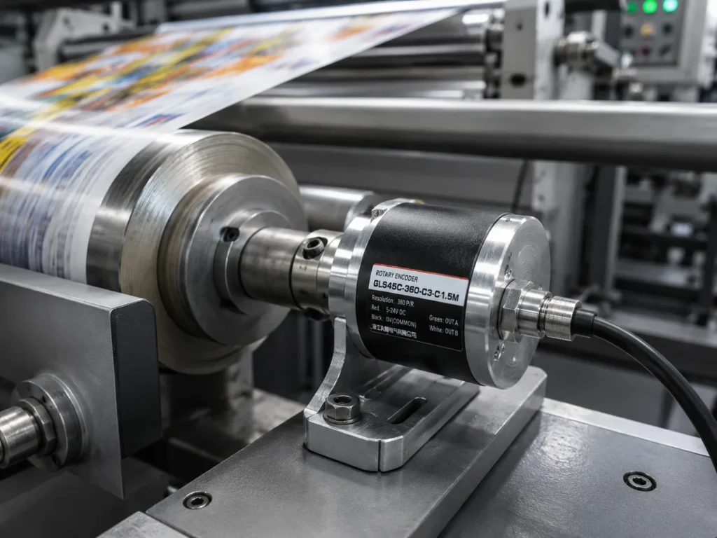
| Compact high-resolution rotary feedback | GLS38AO5 φ38 mm Encoder | Up to 5000 P/R, compact size, suitable for packaging, printing, textile, and robot equipment |
| Servo motor or through-hole installation | GLT48 Through-Hole Encoder | Through-hole configuration and selectable resolutions for servo feedback projects |
| High-resolution and long-distance feedback | GOS40A φ40 mm Rotary Encoder | Up to 10,000 P/R with output options for demanding automation systems |
| Industrial 24V rotary feedback with protection features | GLS50H / GOS5008B Encoder | 24V design, push-pull output, waterproof joint, reverse-polarity protection, and multiple PPR options |
For broader model comparison, look over Catalog to review encoder formats, mounting options, signal configurations, and supporting accessories.
For projects involving custom shaft sizes, mounting arrangements, PPR values, cables, output interfaces, labels, or machine-specific designs, Sensyor also provides ODM/OEM Customization support for equipment manufacturers, industrial distributors, and wholesalers sourcing encoder solutions from China.
Common Mistakes When Choosing a High Precision Encoder
Choosing PPR Before Checking the Controller
A high-PPR encoder can create pulse frequencies that exceed PLC or drive input limits. Always calculate frequency at maximum RPM.
Ignoring the Index Signal
If the machine needs a repeatable home location after startup, A/B alone may not be enough. An ABZ encoder can provide a once-per-revolution reference pulse.
Treating Cable as a Low-Priority Component
A good encoder connected through poor cable routing can still produce poor feedback. Signal quality must be considered from encoder output to controller input.
Forgetting Mechanical Alignment
Misalignment, shaft runout, excessive loading, or unsuitable couplings can reduce encoder life and damage repeatability.
Using a Rotary Encoder to Solve a Linear Measurement Problem
When direct axis position is critical, an optical linear encoder may provide a better measurement strategy than indirect motor-shaft feedback.
The right high precision incremental encoder is not chosen by PPR alone.
Start with the machine motion requirement. Then verify resolution, accuracy expectation, output format, controller capacity, shaft structure, cable length, electrical noise, and installation conditions. That process produces a feedback system that is not only precise on paper, but dependable during real production cycles.
For a closer look at Sensyor’s encoder manufacturing capabilities, engineering background, and industrial sensor portfolio, visit About Sensyor. For a custom encoder requirement, prepare your shaft dimensions, PPR target, output type, voltage, cable length, environmental conditions, and expected annual quantity before sending an inquiry.
FAQ
What is a high precision incremental encoder?
A high precision incremental encoder is a rotary feedback device that generates pulse signals for accurate speed, direction, and relative position measurement. Its real-world performance depends on resolution, accuracy, repeatability, installation quality, output signal, and cable conditions.
Is higher PPR always better for an incremental encoder?
No. Higher PPR provides finer pulse resolution, but it also increases output frequency at higher speeds. The controller, wiring, and output circuit must support that frequency without losing pulses.
What is the difference between a quadrature encoder and an incremental encoder?
An incremental encoder provides relative pulse-based motion feedback. A quadrature encoder is a common incremental encoder type that uses A and B channels offset by 90 degrees to identify rotational direction.
When should I choose Magnetoelectric Encoders instead of optical encoders?
Choose based on the required resolution, mechanical arrangement, operating environment, and signal interface. Magnetoelectric encoders can suit compact and demanding industrial applications, while optical encoders are often selected when high-resolution rotational feedback is required.
Can an incremental encoder be used for long-distance signal transmission?
Yes, but cable type, capacitance, shielding, output voltage, differential signaling, controller input, and EMI conditions must be considered. Long-distance transmission should be validated under actual machine conditions.
When is an optical linear encoder a better choice?
An optical linear encoder is often preferable when direct linear-axis position matters more than motor or screw rotation. It can help reduce the influence of backlash, transmission error, and mechanical variation between the drive motor and moving axis.