
what is High Frequency Counter?sensyor CY7
A CY7 high frequency counter is an electronic instrument that measures the repetition rate of an electrical signal. It counts input pulses during a precisely controlled time interval and converts the result into a frequency reading, usually in hertz (Hz), kilohertz (kHz), or megahertz (MHz). In industrial automation, a counter can turn the pulse output from an encoder, proximity sensor, flow sensor, or controller into useful information about speed, rate, position, production quantity, or machine status.
For engineers and equipment builders, the name can be slightly misleading. “High frequency” does not describe one universal range. A Sensyor RF counter may measure signals in the megahertz or gigahertz range, while an industrial high frequency pulse counter may be considered high speed because it accepts pulses faster than a standard PLC input can reliably process. The correct device therefore depends on the signal source, required measuring range, control function, and installation environment.
What Does a High Frequency Counter Measure?
Frequency describes how many times a periodic event occurs per second. One event per second equals one hertz. If an encoder produces 5,000 pulses in one second, the pulse frequency is 5 kHz. A counter detects the rising or falling edges of those pulses and reports their rate.
Depending on its operating mode, an industrial counter may display or calculate:
- Pulse frequency in Hz or kHz
- Motor or shaft speed in revolutions per minute
- Production rate, flow rate, or line speed
- Total pulse count or batch quantity
- Elapsed time, period, or interval between events
- Alarm and relay states when a preset value is reached
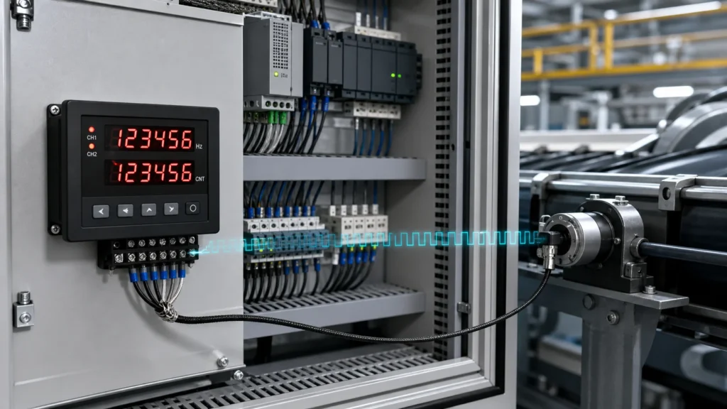
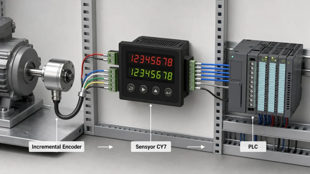
The measurement source is often an encoder. Sensyor’s incremental encoder range generates pulse signals that can be used for speed, direction, and relative-position monitoring. A compatible counter converts those pulses into a value an operator can read or a control system can use.
How Does a High Frequency Counter Work?
The basic direct-counting relationship is simple:
Frequency = Number of detected pulses ÷ Gate time
The gate time is a precisely defined measuring window produced by the counter’s internal timebase. If the input delivers 10,000 pulses while the gate is open for one second, the measured frequency is 10,000 Hz. If the gate remains open for 0.1 second and 1,000 pulses are detected, the result is also 10,000 Hz after scaling.
A practical counter performs several operations before showing that result:
- Signal conditioning: The input circuit converts the sensor waveform into clean logic-level transitions.
- Trigger detection: A comparator or trigger circuit recognizes valid rising or falling edges while rejecting unwanted noise.
- Timebase generation: A stable oscillator creates an accurate gate interval.
- Pulse counting: Digital logic accumulates the valid input events during that interval.
- Calculation and display: A processor scales the count, updates the display, and may compare the value with alarm or control setpoints.
At extremely high input rates, a prescaler or divider may reduce the incoming frequency before the main counting circuit processes it. This approach is common in a high speed frequency counter or RF instrument. Industrial panel counters instead focus on reliable pulse detection, electrical compatibility, rapid display updates, alarms, and integration with factory control equipment.
Direct Counting vs. Reciprocal Measurement
| Method | How It Works | Main Strength | Typical Limitation |
|---|---|---|---|
| Direct counting | Counts input cycles during a fixed gate time | Simple and effective at medium or high frequencies | Low-frequency resolution requires a longer gate time |
| Reciprocal measurement | Measures the time for one or more input cycles and calculates its reciprocal | Strong resolution across a wide frequency range | More complex circuitry and processing |
A high resolution frequency counter is designed to distinguish smaller changes in the measured value. A high precision frequency counter produces closely repeatable readings, while a high accuracy frequency counter produces readings close to the true value. These terms are related but not interchangeable. A display with more digits does not guarantee accuracy if the timebase, input triggering, wiring, or calibration is poor.
What Is a High Frequency Counter IC?
A high frequency counter IC is an integrated circuit used to count fast digital transitions inside an instrument, controller, or custom electronic design. The IC may be a dedicated counter, a timer/counter peripheral within a microcontroller, an FPGA logic block, or a prescaler placed ahead of slower processing circuitry.
An IC alone is not a complete industrial measuring system. Reliable operation also requires input protection, voltage-level conversion, noise filtering, a stable reference clock, power conditioning, a display or communications interface, and suitable firmware. A finished panel counter packages these functions into a device that is easier to install, configure, and maintain.
Where Are High Frequency Counters Used?
High frequency counters are useful wherever recurring electrical pulses represent a physical process. Common industrial applications include:
- Motor speed monitoring: Calculating RPM from encoder pulses and pulses per revolution
- Conveyor and production lines: Measuring line speed, product rate, or batch quantity
- Packaging and printing machinery: Synchronizing feeds, rollers, cutters, and registration systems
- CNC and machine tools: Monitoring spindle speed or pulse-based motion feedback
- PLC commissioning: Comparing sensor outputs with controller readings
- Flow and metering systems: Converting pulse trains into rate or accumulated quantity
- Maintenance and testing: Checking whether an encoder or sensor is producing a stable signal
These applications often combine counters with encoders and mounting components. Sensyor groups counters, wire encoders, handwheel products, and related devices in its industrial automation accessories category. Buyers comparing a broader range can also browse all Sensyor products.
Understanding the Sensyor CY7 High Frequency Counter
The Sensyor CY7 high-frequency counter is a panel-mounted industrial device for pulse and frequency monitoring. It is intended for automation equipment, process monitoring, encoder signal checking, and OEM control-panel integration rather than microwave or laboratory RF analysis.
Published CY7 product information lists a double-row six-digit display, selectable input-frequency ranges from 1 Hz to 10 kHz, voltage and no-voltage input options, relay control configurations, and an optional RS485 communication interface. Power configurations include AC/DC 100–240 V or DC 24 V. The device also provides a 12 V sensor supply, allowing an appropriate external sensor to be powered within the stated load limit.
| CY7 Selection Point | Published Option or Rating | Why It Matters |
|---|---|---|
| Display | Double-row, six digits | Supports clear process-value and setpoint viewing |
| Input-frequency selections | 1 Hz, 30 Hz, 300 Hz, 1 kHz, 5 kHz, or 10 kHz | The configured range must match the maximum expected pulse rate |
| Signal input | Voltage or no-voltage input | Must be compatible with the connected sensor or encoder |
| Control output | Relay-output configurations | Enables alarm or basic process-control actions |
| Communication | Optional RS485 | Supports integration with compatible supervisory systems |
| Panel size | 72 × 72 mm front format | Helps determine cabinet cutout and available installation space |
Specifications and option codes should be confirmed for the exact ordered configuration. Sensyor’s encoder and sensor catalog provides an additional starting point for comparing related equipment, while project-specific electrical and mechanical requirements should be checked with the supplier before purchase.
How to Select the Right High Frequency Pulse Counter
1. Calculate the Maximum Input Frequency
For a rotary encoder, calculate pulse frequency from maximum shaft speed and encoder resolution:
Input frequency (Hz) = RPM × pulses per revolution ÷ 60
For example, a 600 RPM shaft with a 500 P/R encoder produces 5,000 pulses per second on one channel. The counter, wiring, and input mode must all support at least 5 kHz, with a reasonable engineering margin.
2. Confirm Signal Compatibility
Check output type, high and low voltage levels, input impedance, polarity, pulse width, and whether the sensor uses NPN, PNP, push-pull, line-driver, open-collector, or contact output. Never assume that two devices are compatible simply because both describe their terminals as “pulse input” or “pulse output.”
3. Define Resolution, Accuracy, and Update Speed
A longer measurement interval can improve direct-counting resolution but slows display updates. A shorter interval gives a faster response but may make the reading less stable. Choose the balance required by the process. For machine monitoring, a rapid and stable trend may be more useful than many display digits.
4. Review Outputs and Communications
Determine whether the application needs only a display, one or more alarm relays, a control output, or communication with a PLC or supervisory system. If RS485 is required, confirm the supported protocol, register map, baud rate, address settings, and network wiring before integration.
5. Check the Installation Environment
Review panel dimensions, supply voltage, operating temperature, humidity, vibration, electrical noise, enclosure protection, grounding, and cable routing. Keep pulse wiring away from motor power cables and variable-frequency-drive outputs whenever practical.
Common Causes of Incorrect Frequency Readings
- Wrong measuring range: The selected input range is lower than the actual pulse frequency.
- Electrical mismatch: The sensor output voltage or transistor type does not match the counter input.
- Noise and false triggers: Poor shielding or grounding creates extra transitions that the counter interprets as pulses.
- Pulse loss: Narrow pulses, long cables, weak signal levels, or an overloaded sensor output prevent valid detection.
- Incorrect scaling: The pulses-per-revolution or engineering-unit conversion is entered incorrectly.
- Unstable timebase or process: A changing input signal naturally produces a changing result.
- Channel confusion: A/B quadrature signals are counted or scaled differently from a single-channel pulse train.
Commission the system at a known speed or with a verified signal source. Compare the displayed result with the calculated input frequency, then test at several operating points. If a project needs a custom output, label, interface, or mounting arrangement, Sensyor’s technical sales team can review the application details.
Arduino High Frequency Counter vs. Industrial Counter
An Arduino high frequency counter can be useful for learning, prototyping, or building a low-cost test tool. Depending on the board and design, it may use a hardware timer input, external interrupt, comparator, prescaler, or dedicated counter IC. Performance depends on the microcontroller clock, firmware overhead, signal conditioning, timer width, and input waveform.
An industrial counter is usually the better choice for a production machine because it provides protected inputs, defined electrical ratings, panel mounting, a readable display, nonvolatile settings, alarm outputs, and documented environmental limits. An Arduino prototype can prove a concept, but it should not be treated as a drop-in substitute where machine safety, electrical noise immunity, long-term availability, or compliance matters.
Frequently Asked Questions
What is the difference between a frequency counter and a pulse counter?
A frequency counter measures the rate of incoming pulses over time. A pulse counter accumulates the total number of pulses. Many industrial counter products can perform both functions, but the available modes depend on the model.
Can a high frequency counter measure motor RPM?
Yes. When an encoder or sensor produces a known number of pulses per revolution, the counter can scale pulse frequency into RPM. The configured P/R value and the maximum pulse rate must match the application.
Does higher display resolution mean higher accuracy?
No. Display resolution shows how finely a value can be indicated. Accuracy also depends on the timebase, trigger quality, calibration, input signal, noise, and measurement method.
Can the CY7 connect to an incremental encoder?
It can be used with a compatible pulse-output sensor or encoder when the voltage levels, output circuit, input frequency, pulse width, wiring, and power requirements agree. Confirm the exact encoder output and CY7 configuration before connection.
What does “high frequency of flagellar counterclockwise rotations” mean?
This phrase belongs to microbiology and describes how often a flagellum rotates counterclockwise. It is not a type of industrial high frequency counter. A scientific setup might convert such motion into measurable events, but the biological phrase and the electronic instrument are different concepts.
How can I choose between a counter IC and a finished panel counter?
Choose a counter IC when designing custom electronics and when your engineering team can develop the signal conditioning, protection, timebase, firmware, enclosure, and interfaces. Choose a finished panel counter when you need faster integration, operator display, documented inputs, control outputs, and straightforward maintenance.
Conclusion
A frequency counter converts fast electrical events into a frequency, speed, rate, or count that people and control systems can use. Its performance depends not only on counting speed but also on timebase quality, input compatibility, noise control, scaling, resolution, and installation practice. For industrial encoder and pulse-monitoring applications, the Sensyor CY7 offers configurable frequency inputs, a six-digit dual-row display, control outputs, and optional communication in a compact panel format. Review the actual signal and process requirements first, then confirm the exact counter configuration before ordering or wiring the system.