How to measure a high frequency signal?
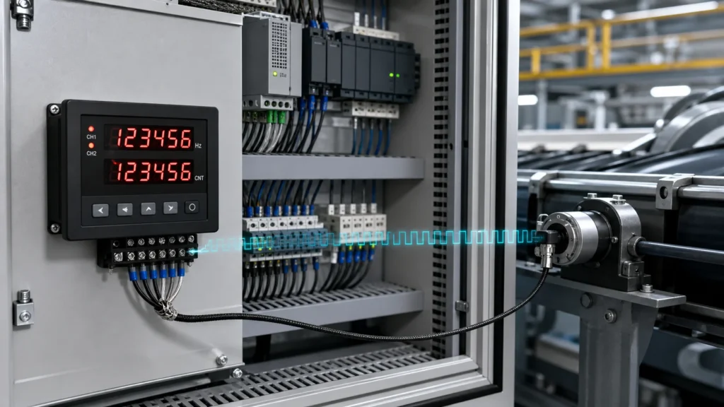
To measure a high frequency signal, first determine whether you need its repetition rate, waveform shape, or spectral content. If you need the number of pulses or cycles per second, a CY7 High Frequency Counter can measure a compatible industrial pulse signal directly. Verify the signal voltage, output type, pulse width, and maximum frequency; connect the source to the correct input; select a suitable range and gate time; apply the required scaling; and compare the reading with a calculated or known reference.
This distinction matters because no single instrument answers every signal question. A frequency counter is ideal for stable periodic pulses. An oscilloscope shows voltage over time and helps reveal ringing, noise, duty cycle, and distorted edges. A spectrum analyzer shows how signal energy is distributed across frequencies. For encoder feedback, speed monitoring, production-rate measurement, and PLC commissioning, a panel counter is often the most direct tool.
What Does Measuring a High Frequency Signal Mean?
Frequency is the number of repeating cycles or pulse events that occur in one second. Its unit is hertz, where 1 Hz equals one event per second. A 5 kHz pulse train produces 5,000 pulses each second. In automation systems, those pulses may come from an incremental encoder, proximity sensor, photoelectric sensor, flow meter, turbine sensor, or controller output.
A counter normally detects rising or falling signal edges during a controlled measurement window known as the gate time:
Frequency (Hz) = Number of detected pulses ÷ Gate time (s)
If the instrument detects 2,500 pulses during a 0.5-second gate, the frequency is 5,000 Hz. The counter repeats the measurement and updates its display. A stable internal timebase, clean trigger transitions, and a compatible input circuit are essential because missed or false edges change the result.
Choose the Correct Measurement Instrument
| Measurement Goal | Recommended Instrument | What It Reveals |
|---|---|---|
| Pulse rate, clock rate, or RPM | Frequency Counter | Cycles or pulses per second, often with a direct digital reading |
| Voltage, waveform shape, duty cycle, or noise | Oscilloscope | Signal amplitude and timing behavior in the time domain |
| Harmonics, spurious signals, or occupied bandwidth | Spectrum analyzer | Amplitude versus frequency |
| Automated sampled measurements | DAQ device or controller counter input | Frequency data that software can log and analyze |
| Industrial pulse display and alarm control | Panel-mounted high frequency pulse counter | Operator display, scaling, presets, and control outputs |
Do not connect an unknown signal before confirming the instrument’s electrical limits. A laboratory RF input, a 24 V industrial pulse input, and a contact input are not interchangeable. When the waveform is unknown, inspect it with a suitably rated oscilloscope and probe before connecting it to a counter.
How to Measure a High Frequency Signal Step by Step
1. Identify the Signal Source
Record the device model, power supply, output circuit, expected amplitude, frequency range, pulse width, and number of channels. For an encoder, also record the pulses per revolution, maximum shaft speed, and whether the output is A, A/B, or A/B/Z.
Output circuits may include NPN open collector, PNP open collector, push-pull, voltage line driver, differential line driver, or mechanical contact. Consult the source and counter documentation rather than relying on wire color alone.
2. Calculate the Expected Maximum Frequency
For a rotary encoder, calculate the single-channel pulse rate before selecting the measuring range:
Pulse frequency (Hz) = Speed (RPM) × Pulses per revolution ÷ 60
For example, a 600 RPM shaft with a 500 P/R encoder produces 5,000 pulses per second on one channel. A 1,000 P/R encoder at the same speed produces 10 kHz. If quadrature edge multiplication is performed elsewhere in the control system, confirm whether its displayed count is based on ×1, ×2, or ×4 decoding; do not assume the panel counter uses the same convention.
A high-resolution encoder can generate a very fast signal even at moderate shaft speed. The GOS40A rotary encoder, for example, is published with resolution options up to 10,000 P/R. At 600 RPM, a 10,000 P/R configuration would produce a 100 kHz single-channel pulse rate, which is beyond the CY7’s published selectable 10 kHz maximum. This calculation prevents an unsuitable device pairing.
3. Verify Input Compatibility
Check the counter’s permitted high and low levels, input impedance, minimum pulse width, maximum frequency, and supported sensor type. Also confirm whether the external sensor can be powered from the counter or needs a separate supply.
The published CY7 information describes voltage input and no-voltage input modes. For voltage input, it lists a high level of DC 5–30 V and a low level of DC 0–2 V. These specifications must be checked against the exact ordered model and the connected sensor. If the source uses a differential line-driver output, an appropriate receiver or compatible counter input may be required.
4. Power Down and Wire the Devices
Disconnect power before making or changing industrial control wiring. Follow the terminal diagram for the exact CY7 option. Connect supply power, signal input, common or ground, and sensor supply only where specified. If relay outputs or RS485 communication are used, wire them separately according to their ratings and terminal assignments.
Use shielded signal cable where electrical noise is likely. Route pulse wiring away from motor leads, contactor wiring, heaters, and variable-frequency-drive output cables. Ground the shield as recommended for the machine’s control architecture; careless multiple-point grounding can create ground-loop current.
5. Select Frequency Mode and Input Range
Choose a range that covers the highest expected input with margin. Sensyor publishes CY7 input-frequency selections of 1 Hz, 30 Hz, 300 Hz, 1 kHz, 5 kHz, and 10 kHz. A 4.2 kHz expected signal should not be configured on a 1 kHz range. Selecting a range much wider than necessary may also affect practical display behavior, so use the most appropriate supported setting.
Verify reset behavior, decimal placement, scaling, alarm thresholds, and output delay before running the machine. Record the final settings for maintenance staff.
6. Choose a Suitable Measurement Time
In direct counting, a longer gate time improves frequency resolution because more cycles are counted. A one-second gate has a basic one-count resolution of 1 Hz, while a 0.1-second gate produces faster updates but a coarser basic result. The best setting depends on whether the process requires a stable display or rapid response.
A high resolution frequency counter may use reciprocal measurement, interpolation, averaging, or a more stable timebase to produce finer readings. Resolution is not the same as accuracy: extra digits do not correct an unstable reference, noisy input, incorrect trigger level, or bad scaling.
7. Start at a Known Operating Point
Power the system and begin at a low, controlled speed or use a calibrated pulse generator if available. Observe whether the display is stable and proportional to changes in the source. If the displayed value is intended to represent RPM rather than Hz, verify the conversion against a known shaft speed.
For servo motor testing, the GLT48 through-hole servo encoder produces incremental feedback signals for compatible control systems. Its resolution and output configuration must be matched to both the controller and measuring device before a counter is connected.
8. Verify the Result Independently
Compare the counter reading with at least one independent reference: a signal generator setting, oscilloscope period measurement, PLC high-speed-counter value, tachometer, or calculated encoder frequency. Test at several operating speeds rather than only one point.
If an oscilloscope shows a period of 200 microseconds, the corresponding frequency is:
Frequency = 1 ÷ 0.0002 s = 5,000 Hz
The counter should show the same frequency within the combined uncertainty, resolution, and stability limits of the test setup.
Using the CY7 High Frequency Counter
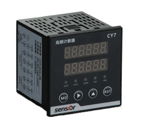
The CY7 High Frequency Counter is designed for industrial pulse measurement, speed monitoring, and control-panel integration. Published information lists a double-row six-digit display, AC/DC 100–240 V or DC 24 V power options, selectable input-frequency ranges up to 10 kHz, relay configurations, a 12 V sensor supply, and optional RS485 communication.
| Application Check | CY7 Published Information | Action Before Use |
|---|---|---|
| Maximum input rate | Selectable ranges through 10 kHz | Calculate worst-case pulse frequency with margin |
| Power supply | AC/DC 100–240 V or DC 24 V options | Confirm the exact model code and cabinet supply |
| Signal level | Voltage and no-voltage input descriptions | Match the sensor output circuit and voltage levels |
| Control | Relay-output options and programmable delay | Check load rating and use an interposing device if required |
| Communication | Optional RS485 interface | Confirm protocol, register map, baud rate, and wiring |
The CY7 is an industrial counter, not a microwave RF instrument. “High speed” is always relative to the application. A high speed frequency counter for radio testing may require a bandwidth of hundreds of megahertz or several gigahertz, while the CY7 focuses on industrial pulses through its published selectable ranges.
Frequency Counter IC vs. Finished Industrial Counter
A high frequency counter IC is a digital component or programmable logic function that counts rapid signal transitions. It may be a dedicated counter chip, a microcontroller timer peripheral, an FPGA counter, or a prescaler that divides an input before processing.
Using an IC provides design flexibility, but it does not eliminate the need for input protection, signal conditioning, isolation where required, a stable timebase, power regulation, firmware, display logic, communications, and an industrial enclosure. A finished counter reduces development effort and provides documented terminals, operating limits, controls, and display functions.
| Option | Best Fit | Main Responsibility |
|---|---|---|
| Counter IC or microcontroller | Custom electronics and embedded products | The designer validates the complete analog and digital measurement chain |
| Laboratory counter | Calibration, RF, oscillator, and bench testing | The user selects bandwidth, impedance, triggering, and timebase performance |
| CY7 industrial panel counter | Encoder pulses, machine speed, rate display, and control panels | The integrator confirms model options, wiring, scaling, and environment |
How to Improve Measurement Accuracy
- Use a clean signal: Correct shielding, grounding, and cable routing reduce false transitions.
- Respect input thresholds: The signal must cross the valid high and low levels reliably.
- Allow adequate pulse width: Pulses narrower than the input can recognize may be missed.
- Select the right range: The expected maximum must stay inside the counter’s rated input range.
- Use sufficient gate time: Longer measurement intervals generally improve direct-counting resolution.
- Check the timebase: Its stability limits the accuracy of the frequency result.
- Prevent mechanical error: Encoder shaft slip, coupling misalignment, and vibration can corrupt the real process signal.
- Verify scaling: Confirm P/R, gear ratio, roller circumference, and engineering units.
Mechanical installation deserves the same attention as electrical measurement. A suitable industrial encoder coupling helps transmit shaft motion while accommodating the alignment limits specified for the installation. Excessive misalignment can damage bearings or create inconsistent feedback.
Troubleshooting Incorrect or Unstable Readings
| Symptom | Likely Cause | Recommended Check |
|---|---|---|
| Display remains at zero | No power, wrong terminal, incompatible output, or missing common | Verify supply and observe the input with a rated meter or oscilloscope |
| Reading is lower than expected | Pulse loss, range limit, narrow pulses, or incorrect P/R | Measure pulse width and frequency at both the source and counter terminal |
| Reading is higher than expected | Noise, ringing, or unintended edge multiplication | Inspect waveform quality, shielding, grounding, and decoding settings |
| Reading fluctuates | Changing machine speed, short gate time, noise, or mechanical slip | Compare with oscilloscope data and increase averaging or gate time if appropriate |
| Correct at low speed but wrong at high speed | Counter bandwidth exceeded or signal integrity deteriorates | Recalculate maximum rate and examine amplitude and edge quality at full speed |
For longer industrial cable runs, select an encoder output suited to the distance and electrical environment. The GLS50H industrial rotary encoder is published with 24 V options, push-pull circuitry, and protection-oriented features, but its precise output selection must still be checked against the counter input.
Why Work with a Sensyor Encoder Manufacturer?
Frequency measurement is reliable only when the sensor, mechanical installation, counter input, and control logic are designed as one signal chain. A Sensyor Encoder Manufacturer configuration can be selected around shaft type, mounting dimensions, P/R, output circuit, cable, supply voltage, and the maximum pulse rate the receiving device can accept.
When requesting a recommendation, provide the machine type, maximum RPM, required resolution, encoder output, cable length, supply voltage, target display unit, alarm requirements, and communications needs. This information allows the encoder and counter configuration to be reviewed before wiring or batch production.
Accurate high-frequency measurement begins with defining the signal and choosing the right tool. Calculate the expected pulse rate, confirm electrical compatibility, wire the system safely, select an appropriate range and measurement interval, and verify the result independently. For industrial encoder pulses within its published range, the CY7 provides a compact display and control platform. Share the complete signal and machine requirements with Sensyor before selection so the encoder, counter, wiring, and output functions operate as a compatible system.
FAQ
Can a Frequency Counter measure a sine wave?
Yes, if its input stage supports the signal amplitude, frequency, impedance, and waveform. The counter conditions the waveform into valid trigger transitions. An industrial pulse input may require an external comparator or signal conditioner for a small analog sine wave.
What is the maximum frequency of the CY7?
Sensyor’s published CY7 information lists selectable INA and INB ranges up to 10 kHz. Confirm the exact model and configuration before ordering because the correct range must exceed the application’s calculated maximum pulse frequency.
How do I convert encoder frequency to RPM?
Use RPM = frequency × 60 ÷ pulses per revolution. Confirm whether the frequency represents one encoder channel and whether any edge multiplication is applied.
Why does a high frequency pulse counter miss pulses?
Common causes include exceeding the rated input frequency, insufficient pulse width, incompatible voltage levels, weak pull-up resistance, long cables, poor grounding, or noise filtering that is unsuitable for the signal.
Is a high resolution frequency counter always more accurate?
No. Resolution is the smallest displayed or detectable change. Accuracy describes closeness to the true value. Timebase stability, triggering, signal integrity, calibration, and measurement method all affect accuracy.
Should I use a counter or an oscilloscope?
Use a counter for an accurate numeric reading of a stable, compatible pulse frequency. Use an oscilloscope when you must verify amplitude, waveform shape, ringing, noise, duty cycle, or pulse width. For commissioning, using both instruments can provide the clearest result.