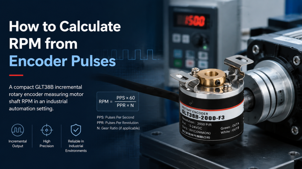
How to Calculate RPM from Encoder Pulses
If you need to know how fast a shaft is spinning, an incremental rotary encoder gives you a stream of pulses — and with the right formula, those pulses translate directly into an RPM value. To calculate RPM from encoder pulses, you divide the number of pulses counted in a known time window by the encoder’s pulses per revolution (PPR), then scale the result to one minute. This guide walks through the formula, two measurement methods, quadrature decoding, gear ratios, and the mistakes that quietly corrupt speed readings.
The RPM Formula for Encoder Pulses
The core relationship is simple: one full shaft revolution produces exactly PPR pulses, so the number of counted pulses divided by PPR gives you revolutions. Convert revolutions-per-window to revolutions-per-minute, and you have the formula:
RPM = (Pulse Count / PPR) × (60 / Time in Seconds)Where:
- Pulse Count — the number of pulses counted during the measurement window.
- PPR — the encoder’s pulses per revolution (its rated resolution, e.g. 100, 600, or 1000).
- Time in Seconds — the duration of the counting window.
- 60 — converts revolutions per second to revolutions per minute.
If your controller samples in milliseconds, use the equivalent form RPM = (Pulse Count / PPR) × (60000 / Time in ms). Both formulas describe the same conversion; pick the one that matches your sampling timer.
What You Need Before You Calculate
The calculation only works when you know three things about your setup. Missing any one of them produces a reading that looks plausible but is wrong.
1. The encoder’s PPR rating
PPR (pulses per revolution) is the number of pulses the encoder outputs for one complete 360° turn of its shaft. It is a published specification you can read from the datasheet — not something you guess from the label. If you are unsure how PPR is defined and how it relates to resolution, the guide to PPR in incremental rotary encoders explains the term in detail.
2. An accurate pulse count
The controller must count every pulse the encoder emits without missing or double-counting. This usually means a hardware counter or an interrupt-driven routine rather than a polling loop, because encoder pulse rates can reach tens of kilohertz at high speeds.
3. A known, stable time window
The window length must be measured accurately — a 10 ms error in a 100 ms window changes the result by 10%. Most PLCs and microcontrollers provide a hardware timer for this.
Method 1: Count Pulses in a Fixed Time Window
This is the most common approach and the one behind the formula above. The controller counts pulses for a fixed window, then calculates RPM.
Worked example
A 600 PPR encoder is connected to a motor. The controller counts 5,000 pulses in a 500 ms window.
RPM = (5000 / 600) × (60 / 0.5)
     = 8.33 revolutions in 0.5 s
     = 16.67 revolutions per second
     = 1000 RPM
The same result comes from the millisecond form: (5000 / 600) × (60000 / 500) = 8.33 × 120 = 1000 RPM.
| PPR | Pulses in 500 ms | Window (s) | Calculated RPM |
|---|---|---|---|
| 600 | 5,000 | 0.5 | 1,000 |
| 1000 | 1,000 | 0.1 | 600 |
| 360 | 3,600 | 1.0 | 600 |
| 2000 | 20,000 | 0.5 | 1,200 |
Frequency measurement is accurate at moderate to high speeds, where many pulses arrive in each window. Its weakness is low speed: if only a few pulses fall inside the window, the result quantizes into coarse steps. A 1000 PPR encoder turning at 1 RPM produces about 16.7 pulses per second — a 100 ms window captures roughly 1 or 2 pulses, so the reading jumps between 0 and 600 RPM. For slow shafts, use the period method below.
Method 2: Measure the Time Between Pulses
Instead of counting pulses in a window, the period method measures the time between two consecutive pulses (or between consecutive position edges) and derives speed from that single interval:
RPM = 60 / (Time Between Pulses in Seconds × PPR)
If the time is measured in microseconds, use RPM = 60000000 / (Time in µs × PPR).
Worked example
A 600 PPR encoder turns slowly, and the controller measures 50 ms between consecutive pulses.
RPM = 60 / (0.05 × 600) = 60 / 30 = 2 RPMOne interval gives one instantaneous speed sample; averaging several intervals smooths the reading. Period measurement excels at low speeds, where each pulse is far apart, but it becomes noisy at high speeds because the interval gets very short. A practical rule of thumb: use frequency measurement for higher speeds and period measurement below roughly a few hundred RPM, or combine both in an M/T method for the widest speed range.
Quadrature Decoding: Why ×4 Changes the Number
Many incremental encoders output two square-wave channels, A and B, offset by 90°. If the controller counts only one edge of one channel, each revolution yields PPR counts. With quadrature decoding, the controller counts rising and falling edges of both A and B, so each revolution yields 4 × PPR counts.
This does not change the physical speed — it multiplies the resolution. When you use quadrature counts in the formula, replace PPR with the effective resolution (4 × PPR), or divide your counted edges by 4 before substituting. For example, a 1000 PPR encoder with fourfold decoding gives 4000 counts per revolution; 12,000 edges counted in 1 second means 12,000 / 4000 = 3 revolutions per second = 180 RPM.
Deciding whether to decode 1×, 2×, or 4× is a practical engineering trade-off — higher multiplication improves resolution but raises the counting frequency the controller must handle. The quadrature encoder signal selection guide walks through the options, and the overview of A, B, and Z output signals shows how to identify each channel.
Accounting for Gear Ratios
Encoders are often mounted on the motor shaft while the load runs through a gearbox. In that case the formula gives the encoder-shaft speed, not the load speed. Multiply by the speed ratio between the two shafts:
Load RPM = Encoder RPM × Speed Ratio- Encoder on the motor, 12:1 reduction to the output shaft → output RPM = encoder RPM ÷ 12 (speed ratio = 1/12).
- Encoder on the output shaft, motor runs 12× faster → motor RPM = encoder RPM × 12.
Getting this backwards is one of the most common causes of speed readings that are off by a factor of the gear ratio, so confirm which shaft the encoder actually rides on before applying any ratio.
Common Mistakes and How to Avoid Them
| Mistake | What happens | Fix |
|---|---|---|
| Using rated PPR with quadrature counts | Speed reads 4× too high | Use effective resolution (4 × PPR) or divide edges by 4 |
| Ignoring the gear ratio | Load speed is wrong by the ratio | Confirm which shaft the encoder is on; apply the ratio |
| Too-short window at low speed | Quantized, jumping RPM values | Lengthen the window or switch to period measurement |
| Polling instead of hardware counting | Missed pulses at high frequency | Use a hardware counter or interrupt-driven routine |
| Wrong time base (ms vs s) | Reading off by 1000× | Keep one formula variant and its units together |
Understanding the signal side helps as well: if the pulses themselves are misread, no formula will save the result. Reviewing how incremental encoders generate pulses makes it easier to spot wiring, noise, and channel problems before they corrupt your counts.
Conclusion
Calculating RPM from encoder pulses comes down to one relationship: divide counted pulses by PPR to get revolutions, then scale to minutes. Count pulses in a fixed window for normal and high speeds, measure the time between pulses for slow shafts, apply 4× the PPR if you decode quadrature edges, and multiply by the speed ratio if a gearbox sits between encoder and load. Nail those four choices and your speed reading will match what the shaft is actually doing.
If you are starting a new measurement project and want the full picture — how incremental rotary encoders work, what the output signals mean, and how to choose the right resolution — the in-depth guide to incremental rotary encoders is a good next stop.
FAQ
How do I calculate RPM from encoder pulses?
Count the pulses in a known time window, divide by the encoder’s PPR to get revolutions, and multiply by 60 divided by the window length in seconds: RPM = (Pulse Count / PPR) × (60 / Time in Seconds).
What is PPR in an encoder?
PPR (pulses per revolution) is the number of output pulses an encoder produces for one full 360° shaft rotation. It is the resolution figure you divide by when converting pulse counts to revolutions.
What is the difference between frequency measurement and period measurement?
Frequency measurement counts pulses in a fixed time window and is best at moderate to high speeds. Period measurement times the gap between consecutive pulses and is more accurate at low speeds, where few pulses arrive per window.
Does quadrature decoding change the RPM result?
No — it changes the resolution, not the speed. Counting all edges of the A and B channels gives 4 × PPR counts per revolution, so you must use the effective resolution (4 × PPR) in the formula to get the correct RPM.
How do I calculate RPM through a gearbox?
Calculate the encoder-shaft RPM first, then multiply by the speed ratio between the encoder shaft and the load shaft. With a 12:1 reduction and the encoder on the motor, the output shaft turns at encoder RPM ÷ 12.
What PPR encoder is suitable for low-speed measurement?
Higher PPR improves low-speed resolution: a 1000 PPR encoder at 1 RPM produces about 16.7 pulses per second, and even then a 100 ms window captures only a few pulses. Use a higher-resolution encoder and period measurement for slow shafts.